- 您現(xiàn)在的位置:買賣IC網(wǎng) > PDF目錄358781 > LFTC-1350 (Electronic Theatre Controls, Inc.) Low Pass Filter(DC to 1350 MHz) PDF資料下載
參數(shù)資料
| 型號(hào): | LFTC-1350 |
| 廠商: | Electronic Theatre Controls, Inc. |
| 英文描述: | Low Pass Filter(DC to 1350 MHz) |
| 中文描述: | 低通濾波器(DC到1350兆赫) |
| 文件頁數(shù): | 1/1頁 |
| 文件大小: | 112K |
| 代理商: | LFTC-1350 |

Low Pass Filter Electrical Specifications (T
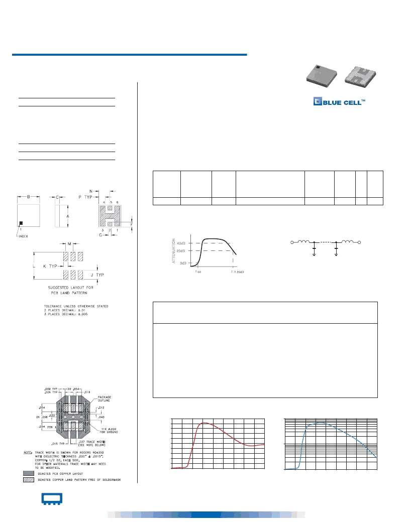
AMB
=25°C)
Maximum Ratings
Operating Temperature
Pin Connections
RF IN
Features
miniature size, 0.15"X0.15"X.028"
low profile, .028" height
high power handling, 15W
7 sections
-55°C to 100°C
Storage Temperature -55°C to 125°C
2**
RF OUT
5**
GROUND
1,3,4,6
** RF IN & RF OUT can be interchanged
Applications
harmonic rejection
internal rejection
receivers & transmitters
Typical Performance Data at 25°C
Frequency
(MHz)
Insertion Loss
(dB)
VSWR
(:1)
1.00
0.06
1.01
1000.00
0.57
1.07
1350.00
0.91
1.25
1550.00
2.76
2.96
1700.00
8.24
10.25
2100.00
23.80
41.48
2700.00
43.89
58.41
4000.00
43.19
62.68
7000.00
23.87
14.62
9000.00
23.66
2.77
LFTC-1350
INSERTION LOSS
0
5
10
15
20
25
30
35
40
45
50
0
1000
2000
3000
4000
5000
6000
7000
8000
9000
FREQUENCY (MHz)
I
LFTC-1350
VSWR
1
10
100
0
1000
2000
3000
4000
5000
6000
7000
8000
9000
FREQUENCY (MHz)
V
CASE STYLE: FR933
PRICE: $3.75 ea. QTY (10-49)
LFTC-1350
* Derate linearly to 7W at 100°C ambient
DC-1350
1550
2100
2700-4000
7000
1.2
15
LF1
7
MODEL
NO.
PASSBAND
(MHz)
(loss < 1 dB)
Typ.
fco, MHz
Nom.
(loss 3 dB)
Typ.
VSWR (:1)
Passband
M
POWER
INPUT*
(W)
STOP BAND (MHz)
Typ.
( > 20 dB) ( loss> 40 dB)
fr20dB
Typ.
N
S
RF IN
RF OUT
schematic
typical frequency response
R 20dB
co
f
f
20dB
3dB
40dB
A
Outline Drawing
Demo Board MCL P/N: TB-233
Suggested PCB Layout (PL-112)
Outline Dimensions ( )
A
B
C
.150
.150
.028
3.81
3.81
0.71
H
J
K
—
.060
.030
.184
—
1.52
0.76
4.67
inch
mm
F
D
—
—
L
E
G
—
—
M
.035
0.89
.028
0.71
N
P
wt.
.050
1.27
.075
1.91
.044 grams
1.12
0.15
DC to 1350 MHz
Low Pass Filter
Ceramic
INTERNET
http://www.minicircuits.com
P.O. Box 350166, Brooklyn, New York 11235-0003 (718) 934-4500 Fax (718) 332-4661
Distribution Centers
NORTH AMERICA 800-654-7949 417-335-5935 Fax 417-335-5945 EUROPE 44-1252-832600 Fax 44-1252-837010
Mini-Circuits
ISO 9001 CERTIFIED
REV. H
M88950
LFTC-1350
EDB-020405
AD/YB/CP
030918
LFTC-1350
NEW!
相關(guān)PDF資料 |
PDF描述 |
|---|---|
| LFZ28V | EMI Common-Mode Suppression Inductors |
| LG-170DGM-CT | LED SMD |
| LG-4801S | DUAL PORT 1000BASE-T TRANSFORMER |
| LG122322 | 122 x 32 dots |
| LG122324 | 122 x 32 dots Built in 8192 Chinese Fonts |
相關(guān)代理商/技術(shù)參數(shù) |
參數(shù)描述 |
|---|---|
| LFTC-1350+ | 制造商:Mini-Circuits 功能描述: |
| LFTC15N19E0897B | 制造商:Murata Manufacturing Co Ltd 功能描述:USE PN LFL21897MTC1A017 - Tape and Reel |
| LFTC15N19E0915B | 制造商:Murata Manufacturing Co Ltd 功能描述:USE PN LFL21915MTC1A027 - Tape and Reel |
| LFTC15N19E0950B | 制造商:Murata Manufacturing Co Ltd 功能描述:USE PN LFL21950MTC1A046 - Tape and Reel |
| LFTC15N19E1441B | 制造商:MUR 功能描述: 制造商:Murata Manufacturing Co Ltd 功能描述: |
發(fā)布緊急采購,3分鐘左右您將得到回復(fù)。