- 您現(xiàn)在的位置:買(mǎi)賣(mài)IC網(wǎng) > PDF目錄367549 > LG1600FXH2488 LG1600FXH Clock and Data Regenerator PDF資料下載
參數(shù)資料
| 型號(hào): | LG1600FXH2488 |
| 英文描述: | LG1600FXH Clock and Data Regenerator |
| 中文描述: | LG1600FXH時(shí)鐘和數(shù)據(jù)再生 |
| 文件頁(yè)數(shù): | 9/20頁(yè) |
| 文件大小: | 492K |
| 代理商: | LG1600FXH2488 |
第1頁(yè)第2頁(yè)第3頁(yè)第4頁(yè)第5頁(yè)第6頁(yè)第7頁(yè)第8頁(yè)當(dāng)前第9頁(yè)第10頁(yè)第11頁(yè)第12頁(yè)第13頁(yè)第14頁(yè)第15頁(yè)第16頁(yè)第17頁(yè)第18頁(yè)第19頁(yè)第20頁(yè)

Data Sheet
August 1999
LG1600FXH Clock and Data Regenerator
9
Lucent Technologies Inc.
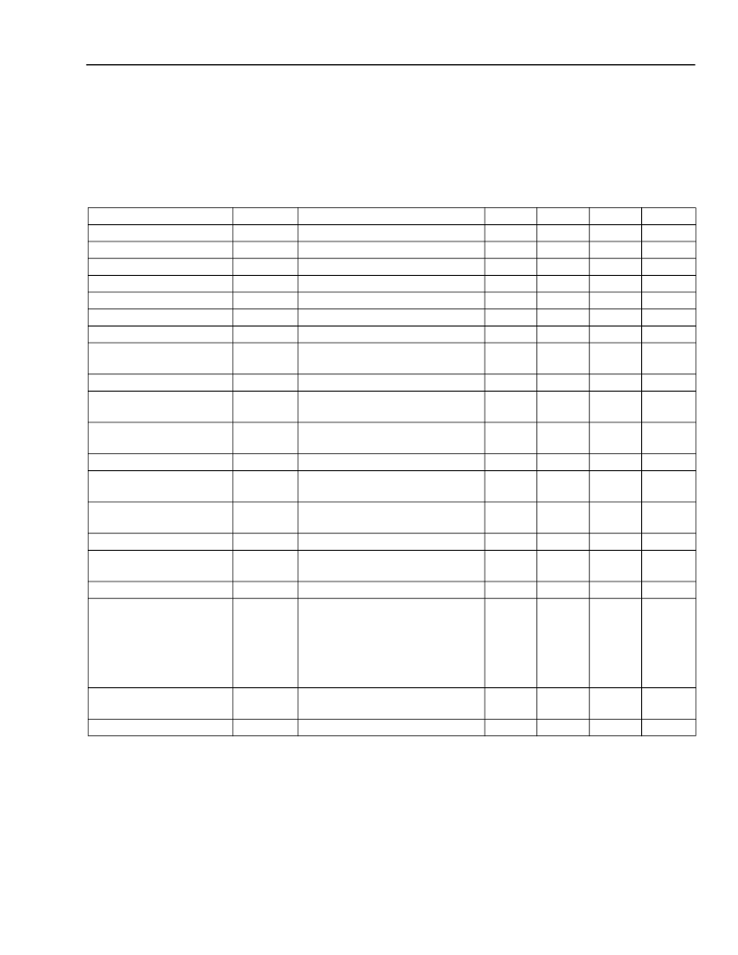
Electrical Characteristics
t
CASE
= 0 °C to 70 °C, V
SS
= –4.7 V to –5.7 V, V
DD
= 5 V, bit rate = f
B
Gbits/s ±0.05% NRZ and data pattern =
2
23
– 1 PRBS, 200 mV
≤
V
±IN
≤
800 mV, BER < 1e
–9
, unless otherwise indicated.
Note:
Minimum and maximum values are testing requirements. Typical values are characteristics of the device and
are the result of engineering evaluations. Typical values are for information purposes only and are not part of
the testing requirements.
Parameter
Symbol
V
–IN
V
+IN –
V
–IN
V
±OUT
V
±OUT
V
±CLKO
V
±CLKO
V
±CLKO
PW%
Conditions
Min
200
200
625
650
650
625
500
90
Typ
—
—
750
800
750
750
600
100
Max
800
1600
900
900
900
900
900
110
Unit
mVp-p
mVp-p
mVp-p
mVp-p
mVp-p
mVp-p
mVp-p
%
Data Input Voltage
Data Input Voltage
Data Output Voltage
Data Output Voltage
Clock Output Voltage
Clock Output Voltage
Clock Output Voltage
Output Pulse Width Rela-
tive to Bit Period T = 1/f
B
Clock Output Duty Cycle
Clock/Data Output Transi-
tion Time
Maximum Bit Error Rate
Single ended on either input
Differential
ac coupled
dc coupled
dc coupled
ac coupled; f
B
≤
3 Gbits/s
ac coupled; f
B
> 3 Gbits/s
t
CASE
= 40 °C
DC
CLKO
t
r
, t
f
t
CASE
= 40 °C
20% to 80%
40
—
—
80
60
100
%
ps
BER
MAX
Jitter modulation @ f
B
×
40 kHz,
t
CASE
= 40 °C
R
L
= 10 k
R
L
= 10 k
, V
–IN
= 0 V
1e
–3
—
—
—
LOS Output Voltage, Low
LOS Output Voltage, High
V
LOSL
V
LOSH
–1
–0.8
V
DD
0.5
V
DD
V
V
V
DD
–
0.5
10
Loss of Signal Delay
τ
LOS
Measured from last data transi-
tion, t
CASE
= 40 °C
—
User adjustable with R
X
as sug-
gested by Figure 8, t
CASE
= 25 °C
Load to ground
≥
20 k
f
mod
≤
f
B
x 40 kHz, t
CASE
= 40 °C
30
100
μs
Jitter Generation
Jitter Transfer Bandwidth
J
GEN
J
BW
—
—
0.005
f
B
0.01
—
UI
MHz
Output Reference Voltage
Jitter Tolerance
V
REF
J
TOL
–3.4
1.5
–3.15
5
–2.9
—
V
UI
f
B
x 40 kHz
≤
f
mod
≤
f
B
×
400 kHz,
t
CASE
= 40 °C
f
mod
≥
f
B
×
400 kHz,
t
CASE
= 40 °C
Measured from first data
transition
*
, t
CASE
= 40 °C
–5.7 V
≤
V
SS
≤
–4.7 V
0.6 f
B
/
f
mod
0.15
2 f
B
/f
mod
0.5
—
—
UI
UI
Acquisition/Recovery
Time
Supply Current
τ
ACQ
* Parameter guaranteed by design or characterization and not production tested.
—
600
800
μs
I
SS
—
290
320
mA
相關(guān)PDF資料 |
PDF描述 |
|---|---|
| LG1600FXH2666 | LG1600FXH Clock and Data Regenerator |
| LG1600KXH | LG1600KXH Clock and Data Regenerator |
| LG1600KXH0622 | LG1600KXH Clock and Data Regenerator |
| LG1600KXH1244 | LG1600KXH Clock and Data Regenerator |
| LG1600KXH1250 | LG1600KXH Clock and Data Regenerator |
相關(guān)代理商/技術(shù)參數(shù) |
參數(shù)描述 |
|---|---|
| LG1600FXH2666 | 制造商:AGERE 制造商全稱(chēng):AGERE 功能描述:LG1600FXH Clock and Data Regenerator |
| LG1600FXH2666TP10 | 制造商:Alcatel-Lucent 功能描述: 制造商:Lucent 功能描述: |
| LG1600FXH2949 | 制造商:AGERE 制造商全稱(chēng):AGERE 功能描述:LG1600FXH Clock and Data Regenerator |
| LG1600FXH3111 | 制造商:AGERE 制造商全稱(chēng):AGERE 功能描述:LG1600FXH Clock and Data Regenerator |
| LG1600FXH3840 | 制造商:AGERE 制造商全稱(chēng):AGERE 功能描述:LG1600FXH Clock and Data Regenerator |
發(fā)布緊急采購(gòu),3分鐘左右您將得到回復(fù)。