- 您現(xiàn)在的位置:買賣IC網(wǎng) > PDF目錄367549 > LG1625AXF (Lineage Power) Laser Driver(激光驅(qū)動器) PDF資料下載
參數(shù)資料
| 型號: | LG1625AXF |
| 廠商: | Lineage Power |
| 英文描述: | Laser Driver(激光驅(qū)動器) |
| 中文描述: | 激光驅(qū)動器(激光驅(qū)動器) |
| 文件頁數(shù): | 12/12頁 |
| 文件大?。?/td> | 363K |
| 代理商: | LG1625AXF |

Data Sheet
June 1999
LG1625AXF Laser Driver
Lucent Technologies Inc. reserves the right to make changes to the product(s) or information contained herein without notice. No liability is assumed as a result of their use or application. No
rights under any patent accompany the sale of any such product(s) or information.
Copyright 1999 Lucent Technologies Inc.
All Rights Reserved
June 1999
DS99-187HSPL
For additional information, contact your Microelectronics Group Account Manager or the following:
INTERNET:
http://www.lucent.com/micro
E-MAIL:
docmaster@micro.lucent.com
N. AMERICA:
Microelectronics Group, Lucent Technologies Inc., 555 Union Boulevard, Room 30L-15P-BA, Allentown, PA 18103
1-800-372-2447
, FAX 610-712-4106 (In CANADA:
1-800-553-2448
, FAX 610-712-4106)
ASIA PACIFIC: Microelectronics Group, Lucent Technologies Singapore Pte. Ltd., 77 Science Park Drive, #03-18 Cintech III, Singapore 118256
Tel. (65) 778 8833
, FAX (65) 777 7495
CHINA:
Microelectronics Group, Lucent Technologies (China) Co., Ltd., A-F2, 23/F, Zao Fong Universe Building, 1800 Zhong Shan Xi Road, Shanghai
200233 P R. China
Tel. (86) 21 6440 0468
,
ext. 316
, FAX (86) 21 6440 0652
JAPAN:
Microelectronics Group, Lucent Technologies Japan Ltd., 7-18, Higashi-Gotanda 2-chome, Shinagawa-ku, Tokyo 141, Japan
Tel. (81) 3 5421 1600
, FAX (81) 3 5421 1700
EUROPE:
Data Requests: MICROELECTRONICS GROUP DATALINE:
Tel. (44) 1189 324 299
, FAX (44) 1189 328 148
Technical Inquiries: GERMANY:
(49) 89 95086 0
(Munich), UNITED KINGDOM:
(44) 1344 865 900
(Ascot),
FRANCE:
(33) 1 40 83 68 00
(Paris), SWEDEN:
(46) 8 594 607 00
(Stockholm), FINLAND:
(358) 9 4354 2800
(Helsinki),
ITALY:
(39) 02 6608131
(Milan), SPAIN:
(34) 1 807 1441
(Madrid)
Appendix
(continued)
Instructions for Use of Test Fixture
(continued)
5. Insert the package into the pressure ring (lid down) with pin 1 located next to the orientation mark and turn on
the vacuum. The vacuum will retain the package in the pressure ring during the following steps.
6. Align the vertically conductive material on the circuit board.
7. Place the pressure ring down over the alignment pins and gently tighten the thumb screws.
8. Remove vacuum, if desired.
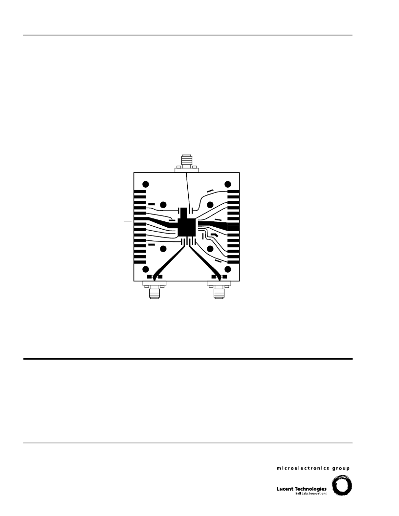
Note: Pressure ring not shown.
5-7874(F)
Figure 11. TF1006A Connector Assignment
DATA IN
(OPTIONAL) V
SS1
NC
GND
MK
MK
GND
(OPTIONAL) V
SS1
V
SS1
(OPTIONAL)
GND
V
TH
V
SS1
V
MOD
V
SS3
V
SS2
V
PRE
GND
OUTPUT
LW5
相關(guān)PDF資料 |
PDF描述 |
|---|---|
| LG5360JM | Optoelectronic |
| LS5360KN | Optoelectronic |
| LGK380E7500 | Optoelectronic |
| LSK382P | Optoelectronic |
| LYK380E7500 | Optoelectronic |
相關(guān)代理商/技術(shù)參數(shù) |
參數(shù)描述 |
|---|---|
| LG1626DXC | 制造商:AGERE 制造商全稱:AGERE 功能描述:LG1626DXC Modulator Driver |
| LG1627BXC | 制造商:AGERE 制造商全稱:AGERE 功能描述:LG1627BXC Clocked Laser Driver |
| LG1628AXA | 制造商:AGERE 制造商全稱:AGERE 功能描述:LG1628AXA SONET/SDH 2.488 Gbits/s Transimpedance Amplifier |
| LG-170-8SEF-CT | 制造商:LIGITEK 制造商全稱:LIGITEK electronics co., ltd. 功能描述:LED SMD |
| LG-170-8UG-CT | 制造商:LIGITEK 制造商全稱:LIGITEK electronics co., ltd. 功能描述:LED SMD |
發(fā)布緊急采購,3分鐘左右您將得到回復。