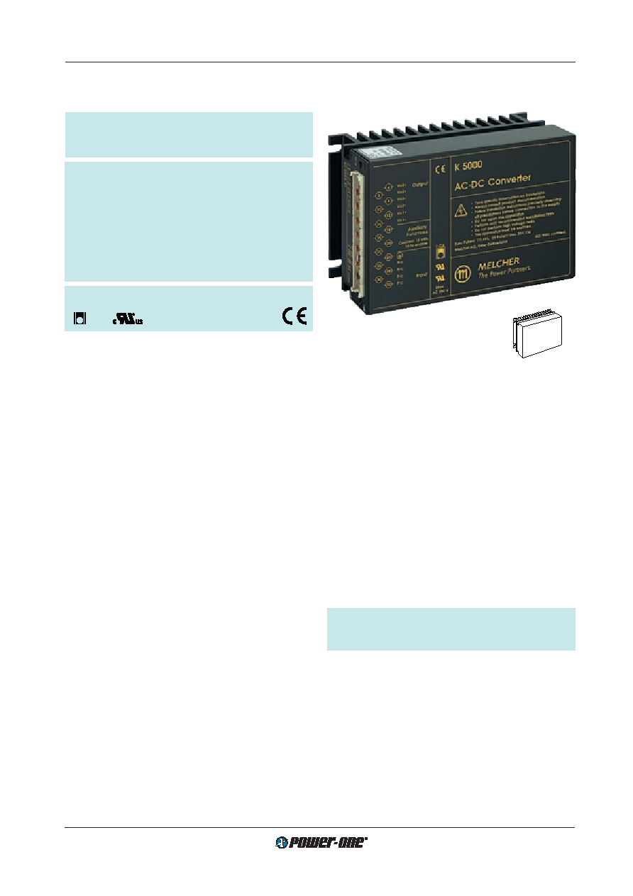
- 您現(xiàn)在的位置:買賣IC網(wǎng) > PDF目錄44114 > LK5320-7EPD3B1 2-OUTPUT 150 W AC-DC PWR FACTOR CORR MODULE PDF資料下載
參數(shù)資料
| 型號: | LK5320-7EPD3B1 |
| 元件分類: | 電源模塊 |
| 英文描述: | 2-OUTPUT 150 W AC-DC PWR FACTOR CORR MODULE |
| 封裝: | METAL, CASE K02, MODULE |
| 文件頁數(shù): | 1/28頁 |
| 文件大?。?/td> | 606K |
| 代理商: | LK5320-7EPD3B1 |
當前第1頁第2頁第3頁第4頁第5頁第6頁第7頁第8頁第9頁第10頁第11頁第12頁第13頁第14頁第15頁第16頁第17頁第18頁第19頁第20頁第21頁第22頁第23頁第24頁第25頁第26頁第27頁第28頁

Cassette Style
150 Watt AC-DC Converters
K Series PFC
Edition 01/01.2001
1/28
150 Watt AC-DC Converters with PFC
K-Series
Universal input voltage range
Power factor
>0.95, harmonics <IEC/EN 61000-3-2
Input over- and undervoltage lock-out
Efcient input lter and built-in surge and transient
suppression circuitry
Fully isolated outputs
Outputs overload, open- and short-circuit proof
No derating over entire operating temperature range
Safety according to IEC/EN 60950
Table of Contents
Page
Summary .......................................................................... 1
Type Survey and Key Data .............................................. 2
Type Key .......................................................................... 2
Functional Description ...................................................... 3
Electrical Input Data ......................................................... 4
Electrical Output Data ...................................................... 6
Auxiliary Functions ......................................................... 12
Summary
The K 4000/5000-series of AC-DC converters represents a
exible range of power supplies for use in advanced elec-
tronic systems. Features include full power factor correc-
tion, high efciency, high reliability, low output voltage noise
and excellent dynamic response to load/line changes.
The converter inputs are protected against surges and tran-
sients occurring at the source lines. An input over- and
undervoltage lock-out circuitry disables the outputs if the
input voltage is outside the specied ranges. Inrush current
limitation is included preventing circuit breakers and fuses
from being damaged at switch-on.
All outputs are overload, open- and short-circuit proof and
are protected against overvoltages by means of a built-in
suppressor diode. The outputs can be inhibited by a logic
signal applied to the connector pin 18 (i). If the inhibit func-
tion is not used pin 18 must be connected with pin 14 to en-
able the outputs.
LED indicators display the status of the converter and allow
visual monitoring of the system at any time.
Full input to output, input to case, output to case and output
to output isolation is provided. The modules are designed
and built according to the international safety standards
IEC/EN 60950 and have been approved by the safety
agencies LGA (Germany) and UL (USA). The UL Mark for
Canada has been ofcially recognized by regulatory au-
thorities in provinces across Canada.
The case design allows operation at nominal load up to
71
°C in a free air ambient temperature. If forced cooling is
provided, the ambient temperature may exceed 71
°C but
the case temperature must remain below 95
°C under all
conditions.
A temperature sensor generates an inhibit signal which
disables the outputs if the case temperature
TC exceeds
the limit. The outputs are automatically re-enabled when
the temperature drops below the limit.
Various options are available to adapt the converters to in-
dividual applications.
The modules may either be plugged into 19 inch rack sys-
tems according to DIN 41494, or be chassis mounted.
Important: These products are intended to replace the
LK 1000 and LK 2000 in order to comply with IEC/EN
61000-3-2.
Page
Electromagnetic Compatibility (EMC) ............................ 16
Immunity to Environmental Conditions ........................... 17
Mechanical Data ............................................................ 18
Safety and Installation Instructions ................................ 19
Description of Options .................................................... 22
Accessories .................................................................... 28
168
6.6"
80
3.2"
16 TE
111
4.4"
3 U
Input voltage range from 85...255 V AC
1or 2 isolated outputs up to 48 V DC
4 kV AC I/O electric strength test voltage
LGA
相關(guān)PDF資料 |
PDF描述 |
|---|---|
| LK5320-7ERD9 | 2-OUTPUT 150 W AC-DC PWR FACTOR CORR MODULE |
| LK5320-7ERTB1 | 2-OUTPUT 150 W AC-DC PWR FACTOR CORR MODULE |
| LK5320-7PD4 | 2-OUTPUT 150 W AC-DC PWR FACTOR CORR MODULE |
| LK5320-7PD5B1 | 2-OUTPUT 150 W AC-DC PWR FACTOR CORR MODULE |
| LK5320-7PD9B1 | 2-OUTPUT 150 W AC-DC PWR FACTOR CORR MODULE |
相關(guān)代理商/技術(shù)參數(shù) |
參數(shù)描述 |
|---|---|
| LK5320-7R | 功能描述:線性和開關(guān)式電源 Euro-Cassette 144W (2x 12V) RoHS:否 制造商:TDK-Lambda 產(chǎn)品:Switching Supplies 開放式框架/封閉式:Enclosed 輸出功率額定值:800 W 輸入電壓:85 VAC to 265 VAC 輸出端數(shù)量:1 輸出電壓(通道 1):20 V 輸出電流(通道 1):40 A 商用/醫(yī)用: 輸出電壓(通道 2): 輸出電流(通道 2): 安裝風格:Rack 長度: 寬度: 高度: |
| LK5320-9ER | 制造商:Power-One 功能描述:AC/DC PS DUAL-OUT 12V/12V 6A/6A 280W 15PIN - Bulk |
| LK-54H-SS18(LF)(SN) | 制造商:JST Manufacturing 功能描述: |
| LK5540-7R | 功能描述:線性和開關(guān)式電源 150W 15V 5A OUT AC-DC CONVERTER RoHS:否 制造商:TDK-Lambda 產(chǎn)品:Switching Supplies 開放式框架/封閉式:Enclosed 輸出功率額定值:800 W 輸入電壓:85 VAC to 265 VAC 輸出端數(shù)量:1 輸出電壓(通道 1):20 V 輸出電流(通道 1):40 A 商用/醫(yī)用: 輸出電壓(通道 2): 輸出電流(通道 2): 安裝風格:Rack 長度: 寬度: 高度: |
| LK5540-9ER | 制造商:Power-One 功能描述:ACDC - Bulk |
發(fā)布緊急采購,3分鐘左右您將得到回復。