- 您現(xiàn)在的位置:買賣IC網(wǎng) > PDF目錄358839 > LM122H-MIL Analog Timer Circuit PDF資料下載
參數(shù)資料
| 型號: | LM122H-MIL |
| 英文描述: | Analog Timer Circuit |
| 中文描述: | 模擬定時器電路 |
| 文件頁數(shù): | 11/14頁 |
| 文件大?。?/td> | 281K |
| 代理商: | LM122H-MIL |
Application Hints
(Continued)
*
Timer Protected
Against Damage
for up to 50V
TL/H/7768–26
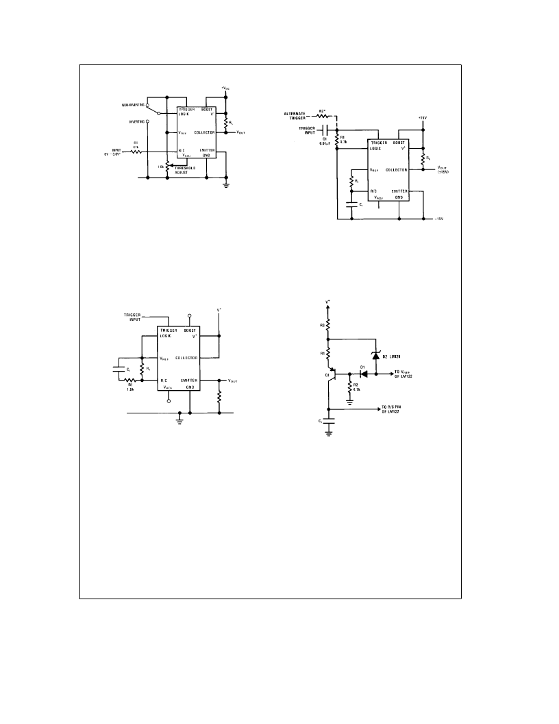
FIGURE 15. Comparator with 0V to 3V Threshold
Eliminating Timing Cycle Upon Initial
Application of Power
The LM122 will normally start a timing cycle (with no trigger
input) when V
a
is first turned on. If this characteristic is
undesirable, it can be defeated by tying the timing capacitor
to V
REF
instead of ground as shown inFigure 16. This con-
nection does not affect operation of the timer in any other
way. If an electrolytic timing capacitor is used, be sure the
negative end is tied to the R/C pin and the positive end to
V
REF
. A 1.0 k
X
resistor should be included in series with the
timing capacitor to limit the surge current load on V
REF
when the capacitor is discharged.
TL/H/7768–27
FIGURE 16. Eliminating Initial Timing Cycle
Using Dual Supplies
The LM122 can be operated off dual supplies as shown in
Figure 17. The only limitation is that the emitter terminal
cannot be tied to ground, it must either drive a load referred
to V
b
or be actually tied to V
b
as shown. Although capaci-
tive coupling is shown for the trigger input (to allow 5V trig-
gering), a resistor can be substituted for C1. R2 must be
chosen to give proper level shifting between the trigger sig-
nal and the trigger pin of the timer. Worst case ‘‘lo’’ on the
trigger pin (with respect to V
b
) is 0.8V, and worst case
‘‘high’’ is 2.5V. R2 may be calculated from the divider equa-
tion with R1 to give these levels.
TL/H/7768–28
*
Select for Proper Level Shift
Emitter Terminal or Emitter Load must be Tied to GND Pin of Timer
FIGURE 17. Operating Off Dual Supplies
Linearizing the Charging Sweep
In some applications (such as a linear pulse width modula-
tor) it may be desirable to have the timing capacitor charge
from a constant current source. A simple way to accomplish
this is shown in Figure 18.
TL/H/7768–29
FIGURE 18. Temperature Compensated
Linear Charging Sweep
Q1 converts the current through R1 to a current source in-
dependent of the voltage across C
t
. R2, R3, D1, and D2 are
added to make the current through R1 independent of sup-
ply variations and temperature changes. (D2 is a low TC
type) D2 and R3 can be omitted if the V
a
supply is stable
and D1 and R2 can be omitted also if temperature stability is
not critical. With D1, D2, R2 and R3 omitted, the current
through R1 will change about 0.015%/
§
C with a 15V supply
and 0.1%/
§
C with a 5.0V supply.
11
相關(guān)PDF資料 |
PDF描述 |
|---|---|
| LM322 | Precision Timers |
| LM323A | 5.0 AMP POSITIVE VOLTAGE REGULATOR |
| LM323H | THREE-TERMINAL POSITIVE FIXED VOLTAGE REGULATORS |
| LM323KSTEEL | THREE-TERMINAL POSITIVE FIXED VOLTAGE REGULATORS |
| LM123KSTEEL-MIL | THREE-TERMINAL POSITIVE FIXED VOLTAGE REGULATORS |
相關(guān)代理商/技術(shù)參數(shù) |
參數(shù)描述 |
|---|---|
| LM122M/IA-MIL | 制造商:QP Semiconductor 功能描述:LM122 883 LEVEL CAN-NSC |
| LM123 | 制造商:SEME-LAB 制造商全稱:Seme LAB 功能描述:3 AMP POSITIVE VOLTAGE REGULATORS |
| LM123-05 | 制造商:SEME-LAB 制造商全稱:Seme LAB 功能描述:3 AMP POSITIVE VOLTAGE REGULATORS |
| LM123-12 | 制造商:SEME-LAB 制造商全稱:Seme LAB 功能描述:3 AMP POSITIVE VOLTAGE REGULATORS |
| LM123-15 | 制造商:SEME-LAB 制造商全稱:Seme LAB 功能描述:3 AMP POSITIVE VOLTAGE REGULATORS |
發(fā)布緊急采購,3分鐘左右您將得到回復(fù)。