- 您現(xiàn)在的位置:買賣IC網(wǎng) > PDF目錄360883 > LM137ASMD05 Voltage Regulator PDF資料下載
參數(shù)資料
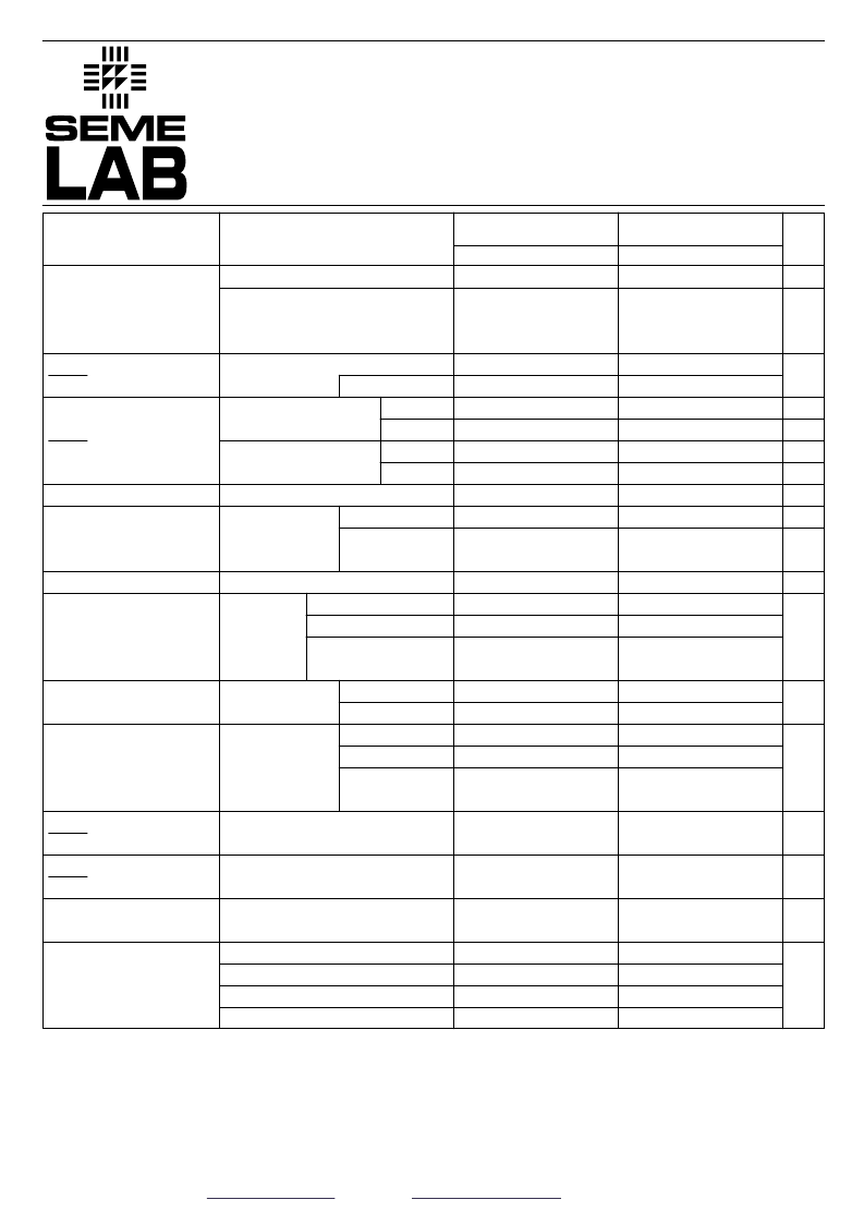
| 型號: | LM137ASMD05 |
| 英文描述: | Voltage Regulator |
| 中文描述: | 電壓調(diào)節(jié)器 |
| 文件頁數(shù): | 2/4頁 |
| 文件大小: | 42K |
| 代理商: | LM137ASMD05 |
Document Number 2831
Issue 2
IP137
A
SERIES
IP137A SERIES
IP337
A
SERIES
IP337A SERIES
LM137
A
SERIES
LM137A SERIES
Semelab plc.
Telephone +44(0)1455 556565. Fax +44(0)1455 552612.
E-mail:
sales@semelab.co.uk
Website:
http://www.semelab.co.uk
Semelab Plc reserves the right to change test conditions, parameter limits and package dimensions without notice. Information furnished by Semelab is believed
to be both accurate and reliable at the time of going to press. However Semelab assumes no responsibility for any errors or omissions discovered in its use.
Semelab encourages customers to verify that datasheets are current before placing orders.
1)
Regulation is measured at constant junction temperature, using pulse testing at a low duty cycle. Changes in output voltage due to heating effects are covered under
thermal regulation specifications. Load regulation is measured at a point 1/8
”
from the bottom of the package for the TO
–
3 and TO
–
66 packages, at the junction of the
wide and narrow portion of the output lead for the SMD packages, and 1/8
”
below the base of the package on the output pin of the TO
–
257 package.
2) Test Conditions unless otherwise stated: VIN
–
VOUT= 5V , IOUT= 0.5A , PMAX= 20W , IMAX= 1.5A, VMAX= 40V for standard series , 50V for HV series.
IP137A , IP137AHV
LM137A , LM137AHV
Min.
Typ.
-1.238
-1.25
IP137 , IP137HV
LM137 , LM137HV
Min.
Typ.
-1.225
-1.25
Parameter
Test Conditions
I
OUT
= 10mA
I
OUT
= 10mA to I
MAX
V
IN
–
V
OUT
= 3V to V
MAX
P
≤
P
MAX
V
IN
–
V
OUT
= 3V to V
MAX
Max.
-1.262
Max.
-1.275
Units
V
T
J
= -55 to 150
°
C
T
J
= -55 to 150
°
C
V
OUT
≤
5V
V
OUT
≥
5V
V
OUT
≤
5V
V
OUT
≥
5V
T
A
= 25
°
C
C
ADJ
= 0
C
ADJ
= 10
μ
F
T
J
= -55 to 150
°
C
I
OUT
= 10mA to I
MAX
I
OUT
= 10mA to I
MAX
T
J
= -55 to 150
°
C
t
p
= 10ms
V
OUT
= -10V
f = 120Hz
T
J
= -55 to 150
°
C
I
OUT
= 10mA to I
MAX
V
IN
–
V
OUT
= 3V to 40V
V
IN
–
V
OUT
= 3V to 50V
(HV SERIES)
V
IN
–
V
OUT
≤
40V
V
IN
–
V
OUT
≤
10V
V
IN
–
V
OUT
≤
15V
V
IN
–
V
OUT
= 40V
V
IN
–
V
OUT
= 50V
(HV SERIES)
T
J
= -55
to 150
°
C
T
J
= -55 to 150
°
C
T
J
= -55 to 150
°
C
T
J
= -55 to 150
°
C
T
A
= +125
°
C
t = 1000 Hrs
f = 10 Hz to 10 kHz
T
A
= 25
°
C
K Package
R Package
G Package
LCC4 Package
-1.200
-1.250
-1.300
0.010
0.020
15
0.3
20
0.3
0.002
60
0.020
0.050
25
0.5
50
1
0.02
66
77
65
0.5
2
100
5
5
3
6
2.5
1.2
2.2
0.4
5
3
1.5
0.24
3.2
0.2
0.4
0.8
0.6
0.3
1
0.003
2.3
5
3
3
7
5
13
-1.220
-1.25
-1.280
0.005
0.010
5
0.1
10
0.2
0.002
66
0.010
0.030
25
0.5
50
1
0.020
60
70
80
65
0.2
1.0
100
2
5
2.0
6
2.5
1.2
2.2
0.4
5
3
1.5
0.24
3.2
1
0.2
0.4
0.8
0.6
1.5
0.3
1
0.003
2.3
5
3
3
7
5
13
V
REF
Reference Voltage
V
OUT
I
OUT
Line Regulation
1
V
OUT
I
OUT
Load Regulation
1
Thermal Regulation
Ripple Rejection
I
ADJ
Adjust Pin Current
I
ADJ
Adjust Pin Current
Change
I
MIN
Minimum Load
Current
I
CL
Current Limit
V
OUT
Temperature
TEMP Stability
V
OUT
Long Term Stability
TIME
e
n
RMS Output Noise
(% of V
OUT
)
R
θ
JC
Thermal Resistance
Junction to Case
V
%/V
mV
%
mV
%
%/W
dB
dB
μ
A
μ
A
mA
A
%
%
%
°
C/W
相關PDF資料 |
PDF描述 |
|---|---|
| LM137ASMD05-8QR-B | Voltage Regulator |
| LM137ASMD-8QR-B | Voltage Regulator |
| LM137G | Voltage Regulator |
| LM137HVG | Voltage Regulator |
| LM137SMD-8QR-B | Voltage Regulator |
相關代理商/技術參數(shù) |
參數(shù)描述 |
|---|---|
| LM137ASMD05-8QR-B | 制造商:未知廠家 制造商全稱:未知廠家 功能描述:Voltage Regulator |
| LM137ASMD-8QR-B | 制造商:未知廠家 制造商全稱:未知廠家 功能描述:Voltage Regulator |
| LM137E | 制造商:Brady Corporation 功能描述: |
| LM137G | 制造商:SEME-LAB 制造商全稱:Seme LAB 功能描述:1.5 AMP NEGATIVE ADJUSTABLE VOLTAGE REGULATOR |
| LM137H | 功能描述:線性穩(wěn)壓器 - 標準 RoHS:否 制造商:STMicroelectronics 輸出類型: 極性: 輸出電壓:1.8 V 輸出電流:150 mA 負載調(diào)節(jié): 最大輸入電壓:5.5 V 線路調(diào)整率: 最大工作溫度:+ 125 C 安裝風格:SMD/SMT 封裝 / 箱體:SOT-323-5L |
發(fā)布緊急采購,3分鐘左右您將得到回復。