- 您現(xiàn)在的位置:買賣IC網(wǎng) > PDF目錄358828 > LM2710MT-ADJ (NATIONAL SEMICONDUCTOR CORP) CAP 1000PF 200V 200V X7R RAD.20 .20X.20 BULK S-MIL-PRF-39014 STANDOFF PDF資料下載
參數(shù)資料
| 型號: | LM2710MT-ADJ |
| 廠商: | NATIONAL SEMICONDUCTOR CORP |
| 元件分類: | 穩(wěn)壓器 |
| 英文描述: | CAP 1000PF 200V 200V X7R RAD.20 .20X.20 BULK S-MIL-PRF-39014 STANDOFF |
| 中文描述: | 1.4 A SWITCHING REGULATOR, 1500 kHz SWITCHING FREQ-MAX, PDSO20 |
| 封裝: | TSSOP-20 |
| 文件頁數(shù): | 13/20頁 |
| 文件大?。?/td> | 853K |
| 代理商: | LM2710MT-ADJ |

Operation
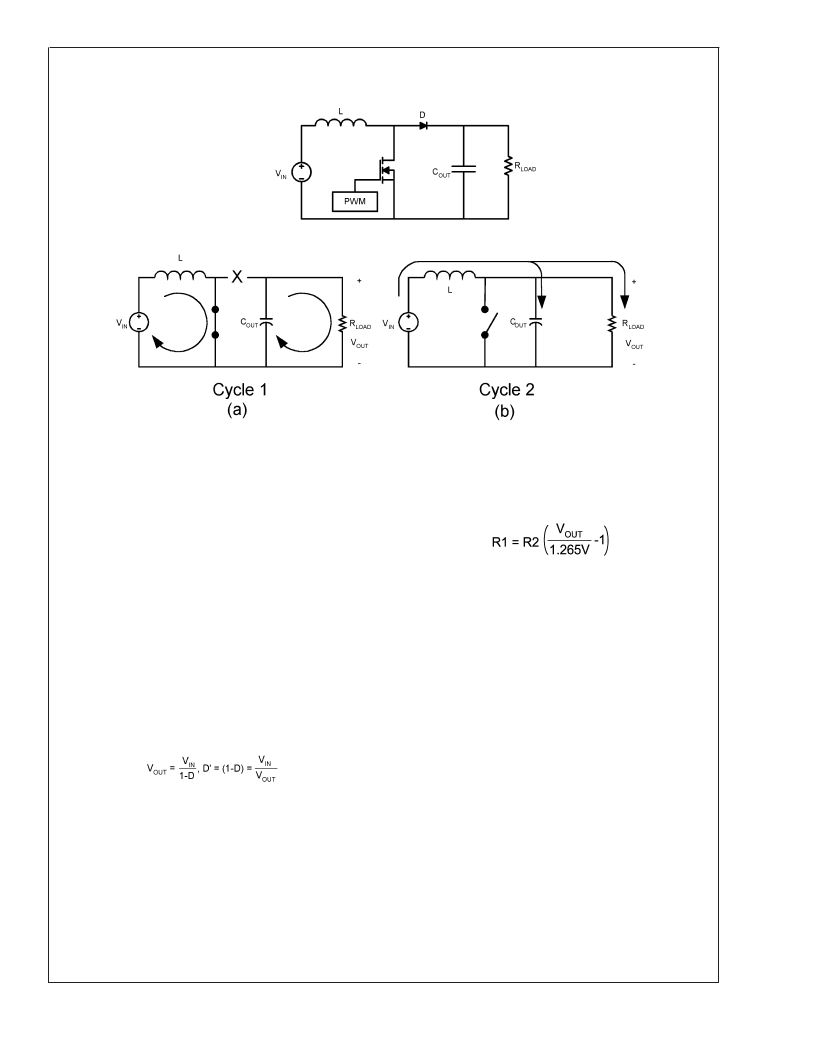
CONTINUOUS CONDUCTION MODE
The LM2710 is a current-mode, PWM boost regulator. A
boost regulator steps the input voltage up to a higher output
voltage. In continuous conduction mode (when the inductor
current never reaches zero at steady state), the boost regu-
lator operates in two cycles.
In the first cycle of operation, shown in
Figure 1
(a), the
transistor is closed and the diode is reverse biased. Energy
is collected in the inductor and the load current is supplied by
C
OUT
.
The second cycle is shown in
Figure 1
(b). During this cycle,
the transistor is open and the diode is forward biased. The
energy stored in the inductor is transferred to the load and
output capacitor.
The ratio of these two cycles determines the output voltage.
The output voltage is defined approximately as:
where D is the duty cycle of the switch, D and D' will be
required for design calculations
SETTING THE OUTPUT VOLTAGE
The output voltage is set using the feedback pin and a
resistor divider connected to the output as shown in the
typical operating circuit. The feedback pin voltage is 1.265V,
so the ratio of the feedback resistors sets the output voltage
according to the following equation:
SOFT-START CAPACITOR
The LM2710 has patented internal circuitry that is used to
limit the inductor inrush current on start-up. This inrush
current limiting circuitry serves as a soft-start. However,
many applications may require much more soft-start than
what is available with the internal circuitry. The external SS
pin is used to tailor the soft-start for a specific application. A
11μA current charges the external soft-start capacitor, Css.
The soft-start time can be estimated as:
Tss = Css*0.6V/11μA
The minimum soft-start time is set by the internal soft-start
circuitry, typically 7ms for 600kHz operation and approxi-
mately half that for 1.25MHz operation. Only longer soft-start
times may be implemented using the SS pin and a capacitor
C
SS
. If a shorter time is designed for using the above equa-
tion, the internal soft-start circuitry will override it.
Due to the unique nature of the dual internal/external soft-
start, care was taken in the design to ensure temperature
stable operation. As you can see with the Iss data in the
Electrical Characterisitcs table and the graph "Soft-Start
Current vs. V
" in the
Typical Performance Characterisitcs
section, the soft start curent has a temperature coefficient
and would lead one to believe there would be significant
variation with temperature. Though the current has a tem-
perature coefficient the actual programmed external soft
start time does not show this extreme of a temperature
variation. As you can see in the following transient plots:
20043402
FIGURE 1. Simplified Boost Converter Diagram
(a) First Cycle of Operation (b) Second Cycle Of Operation
L
www.national.com
13
相關(guān)PDF資料 |
PDF描述 |
|---|---|
| LM2710MTX-ADJ | Step-up PWM DC/DC Converter Integrated with 5 Buffers |
| LM2710 | Step-up PWM DC/DC Converter Integrated with 5 Buffers |
| LM2711MT-ADJ | TFT Panel Module |
| LM2711MTX-ADJ | TFT Panel Module |
| LM2711 | TFT Panel Module |
相關(guān)代理商/技術(shù)參數(shù) |
參數(shù)描述 |
|---|---|
| LM2710MTX-ADJ | 制造商:NSC 制造商全稱:National Semiconductor 功能描述:Step-up PWM DC/DC Converter Integrated with 5 Buffers |
| LM2711 | 制造商:NSC 制造商全稱:National Semiconductor 功能描述:TFT Panel Module |
| LM2711A-ADJ WAF | 制造商:Texas Instruments 功能描述: |
| LM2711MT-ADJ | 制造商:NSC 制造商全稱:National Semiconductor 功能描述:TFT Panel Module |
| LM2711MTX-ADJ | 制造商:NSC 制造商全稱:National Semiconductor 功能描述:TFT Panel Module |
發(fā)布緊急采購,3分鐘左右您將得到回復(fù)。