- 您現(xiàn)在的位置:買賣IC網(wǎng) > PDF目錄361029 > LM4862 (National Semiconductor Corporation) 675 mW Audio Power Amplifier with Shutdown Mode PDF資料下載
參數(shù)資料
| 型號(hào): | LM4862 |
| 廠商: | National Semiconductor Corporation |
| 英文描述: | 675 mW Audio Power Amplifier with Shutdown Mode |
| 中文描述: | 675毫瓦音頻功率放大器關(guān)斷模式 |
| 文件頁數(shù): | 8/10頁 |
| 文件大小: | 262K |
| 代理商: | LM4862 |
Application Information
(Continued)
AUDIO POWER AMPLIFIER DESIGN
Design a 500 mW/8
Audio Amplifier
Given:
Power Output
Load Impedance
Input Level
Input Impedance
Bandwidth
500 mWrms
8
1 Vrms
20 k
100 Hz–20 kHz
±
0.25 dB
A designer must first determine the minimum supply rail to
obtain the specified output power. By extrapolating from the
Output Power vs Supply Voltage graphs in the
Typical Per-
formance Characteristics
section, the supply rail can be
easily found. A second way to determine the minimum sup-
ply rail is to calculate the required V
using equation 3
and add the dropout voltage. Using this method, the mini-
mum supply voltage would be (V
+ (2
*
V
)), where
V
is extrapolated from the Dropout Voltage vs Supply Volt-
age curve in the
Typical Performance Characteristics
sec-
tion.
(3)
Using the Output Power vs Supply Voltage graph for an 8
load, the minimum supply rail is 4.3V. But since 5V is a stan-
dard supply voltage in most applications, it is chosen for the
supply rail. Extra supply voltage creates headroom that al-
lows the LM4862 to reproduce peaks in excess of 500 mW
without clipping the signal. At this time, the designer must
make sure that the power supply choice along with the out-
put impedance does not violate the conditions explained in
the
Power Dissipation
section.
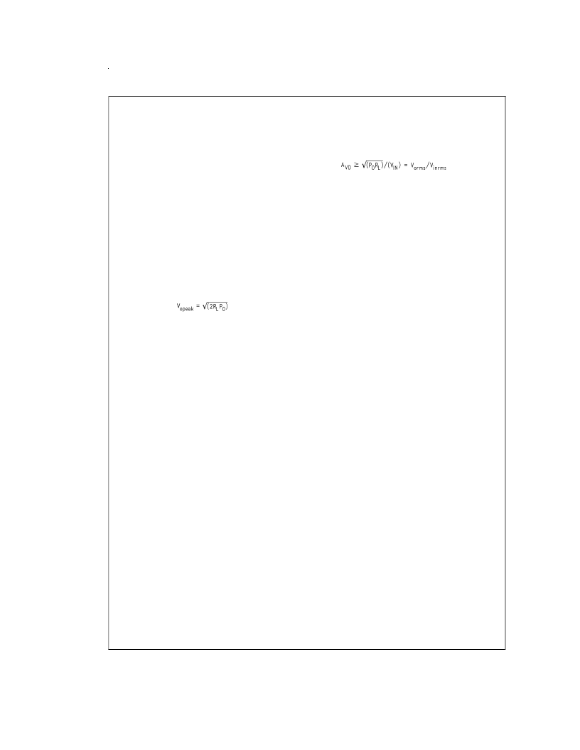
Once the power dissipation equations have been addressed,
the required differential gain can be determined from Equa-
tion 4.
(4)
R
f
/R
i
= A
VD
/2:
(5)
From equation 4, the minimum A
VD
is 2; use A
VD
= 2.
Since the desired input impedance was 20 k
, and with a
A
of 2, a ratio of 1:1 of R
to R
results in an allocation of R
i
= R
= 20 k
. The final design step is to address the band-
width requirements which must be stated as a pair of 3 dB
frequency points. Five times away from a 3 dB point is
0.17 dB down from passband response which is better than
the required
±
0.25 dB specified. This fact results in a low
and high frequency pole of 20 Hz and 100 kHz respectively.
As stated in the
External Components
section, R
i
in con-
junction with C
i
create a highpass filter.
C
i
≥
1/(2
π
*
20 k
*
20 Hz) = 0.397 μF; use 0.39 μF.
The high frequency pole is determined by the product of the
desired high frequency pole, f
, and the differential gain,
A
. With an A
= 2 and f
= 100 kHz, the resulting GBWP
=100 kHz which is much smaller than the LM4862 GBWP of
12.5 MHz. This figure displays that if a designer has a need
to design an amplifier with a higher differential gain, the
LM4862 can still be used without running into bandwidth
problems.
www.national.com
8
相關(guān)PDF資料 |
PDF描述 |
|---|---|
| LM4862M | 675 mW Audio Power Amplifier with Shutdown Mode |
| LM4863 | Dual 2.2W Audio Amplifier Plus Stereo Headphone Function |
| LM4863M | Dual 2.2W Audio Amplifier Plus Stereo Headphone Function |
| LM4863MT | Dual 2.2W Audio Amplifier Plus Stereo Headphone Function |
| LM4863MTE | Dual 2.2W Audio Amplifier Plus Stereo Headphone Function |
相關(guān)代理商/技術(shù)參數(shù) |
參數(shù)描述 |
|---|---|
| LM4862G-D08-T | 制造商:UTC-IC 制造商全稱:UTC-IC 功能描述:AUDIO POWER AMPLIFIER WITH SHUTDOWN MODE |
| LM4862G-S08-R | 制造商:UTC-IC 制造商全稱:UTC-IC 功能描述:AUDIO POWER AMPLIFIER WITH SHUTDOWN MODE |
| LM4862L-D08-T | 制造商:UTC-IC 制造商全稱:UTC-IC 功能描述:AUDIO POWER AMPLIFIER WITH SHUTDOWN MODE |
| LM4862L-S08-R | 制造商:UTC-IC 制造商全稱:UTC-IC 功能描述:AUDIO POWER AMPLIFIER WITH SHUTDOWN MODE |
| LM4862M | 功能描述:音頻放大器 RoHS:否 制造商:STMicroelectronics 產(chǎn)品:General Purpose Audio Amplifiers 輸出類型:Digital 輸出功率: THD + 噪聲: 工作電源電壓:3.3 V 電源電流: 最大功率耗散: 最大工作溫度: 安裝風(fēng)格:SMD/SMT 封裝 / 箱體:TQFP-64 封裝:Reel |
發(fā)布緊急采購,3分鐘左右您將得到回復(fù)。