- 您現(xiàn)在的位置:買賣IC網(wǎng) > PDF目錄361034 > LM82 (National Semiconductor Corporation) Remote Diode and Local Digital Temperature Sensor with Two-Wire Interface PDF資料下載
參數(shù)資料
| 型號: | LM82 |
| 廠商: | National Semiconductor Corporation |
| 元件分類: | 溫度/濕度傳感器 |
| 英文描述: | Remote Diode and Local Digital Temperature Sensor with Two-Wire Interface |
| 中文描述: | 遠(yuǎn)程二極管和本地數(shù)字溫度傳感器兩線接口 |
| 文件頁數(shù): | 8/17頁 |
| 文件大?。?/td> | 341K |
| 代理商: | LM82 |
Logic Electrical Characteristics
(Continued)
Note 6:
Typicals are at T
A
= 25C and represent most likely parametric norm.
Note 7:
Limits are guaranteed to National’s AOQL (Average Outgoing Quality Level).
Note 8:
The Temperature Error will vary less than
±
1.0C for a variation in V
CC
of 3V to 3.6V from the nominal of 3.3V.
Note 9:
Quiescent current will not increase substantially with an active SMBus.
Note 10:
This specification is provided only to indicate how often temperature data is updated. The LM82 can be read at any time without regard to conversion state
(and will yield last conversion result).
Note 11:
Default values set at power up.
Note 12:
Holding the SMBData and/or SMBCLK lines Low for a time interval greater than t
TIMEOUT
will cause the LM82 to reset SMBData and SMBCLK to the IDLE
state of an SMBus communication (SMBCLK and SMBData set High).
1.0 Functional Description
The LM82 temperature sensor incorporates a band-gap type
temperature sensor using a Local or Remote diode and an
8-bit ADC (Delta-Sigma Analog-to-Digital Converter). The
LM82 is compatible with the serial SMBus and I
2
C two wire
interfaces. Digital comparators compare Local (LT) and Re-
mote (RT) temperature readings to user-programmable set-
points (LHS, RHS, and TCS). Activation of the INT output in-
dicates that a comparison is greater than the limit preset in a
HIGH register. The T_CRIT setpoint (TCS) interacts with all
the temperature readings.Activation of the T_CRIT_A output
indicates that any or all of the temperature readings have ex-
ceed the T_CRIT setpoint.
1.1 CONVERSION SEQUENCE
The LM82 converts its own temperature as well as a remote
diode temperature in the following sequence:
1.
Local Temperature (LT)
2.
Remote Diode (RT)
This round robin sequence takes approximately 480 ms to
complete.
1.2 INT OUTPUT and T_HIGH LIMITS
Each temperature reading (LT, and RT) is associated with a
T_HIGH setpoint register (LHS, RHS). At the end of a tem-
perature reading a digital comparison determines whether
that reading has exceeded its HIGH setpoint. If the tempera-
ture reading is greater than the HIGH setpoint, a bit is set in
one of the Status Registers, to indicate which temperature
reading, and the INT output is activated.
Local and remote temperature diodes are sampled in se-
quence by the A/D converter. The INT output and the Status
Register flags are updated at the completion of a conversion,
which occurs approximately 60 ms after a temperature diode
is sampled. INT is deactivated when the Status Register,
containing the set bit, is read and a temperature reading is
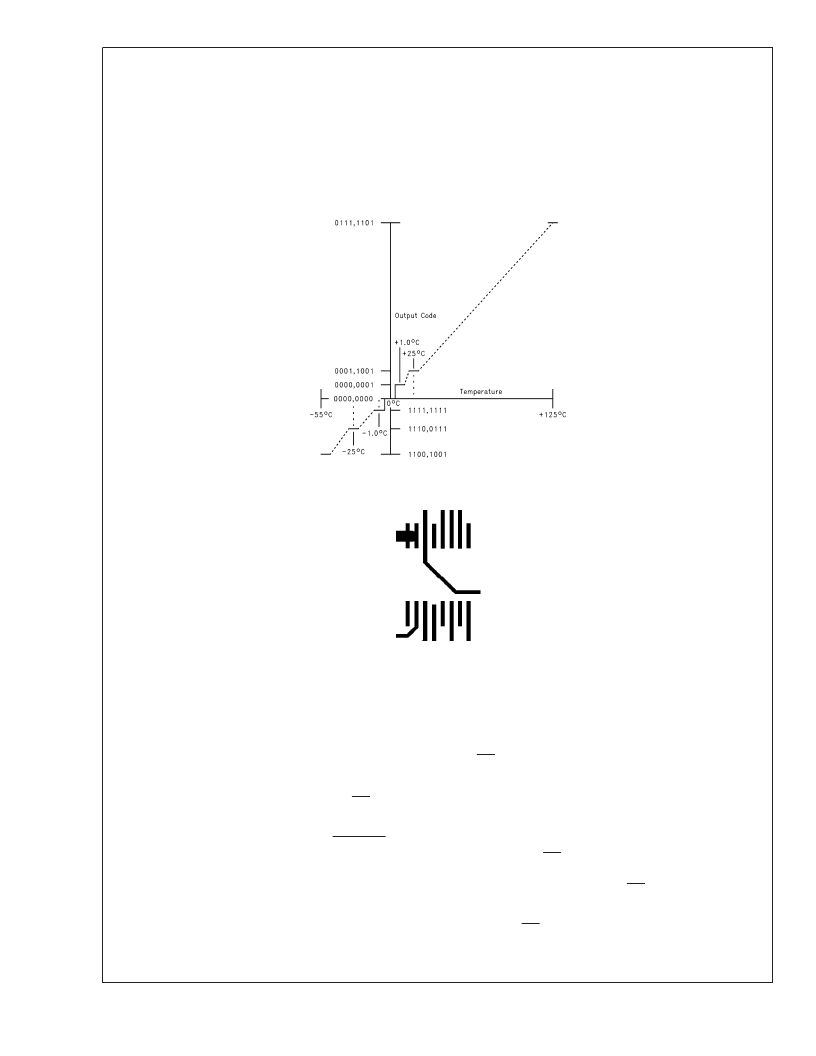
DS101297-5
FIGURE 2. Temperature-to-Digital Transfer Function (Non-linear scale for clarity)
DS101297-24
FIGURE 3. Printed Circuit Board Used for Thermal Resistance Specifications
L
www.national.com
8
相關(guān)PDF資料 |
PDF描述 |
|---|---|
| LM8300HVA9 | Four Wire Resistive Touchscreen Controller with Brownout |
| LM8300ILQ9 | Four Wire Resistive Touchscreen Controller with Brownout |
| LM8300IMT9 | Four Wire Resistive Touchscreen Controller with Brownout |
| LM8300IVA9 | Four Wire Resistive Touchscreen Controller with Brownout |
| LM8300 | Four Wire Resistive Touchscreen Controller with Brownout |
相關(guān)代理商/技術(shù)參數(shù) |
參數(shù)描述 |
|---|---|
| LM82_04 | 制造商:NSC 制造商全稱:National Semiconductor 功能描述:Remote Diode and Local Digital Temperature Sensor with Two-Wire Interface |
| LM8204 | 制造商:未知廠家 制造商全稱:未知廠家 功能描述:電話機(jī)集成電路互換表 |
| LM8207 | 制造商:NSC 制造商全稱:National Semiconductor 功能描述:TFT 18 Gamma Buffer + VCOM Driver + Voltage Reference |
| LM8207MT | 功能描述:LCD 驅(qū)動器 RoHS:否 制造商:Maxim Integrated 數(shù)位數(shù)量:4.5 片段數(shù)量:30 最大時鐘頻率:19 KHz 工作電源電壓:3 V to 3.6 V 最大工作溫度:+ 85 C 最小工作溫度:- 20 C 封裝 / 箱體:PDIP-40 封裝:Tube |
| LM8207MT/NOPB | 功能描述:LCD Gamma緩沖器 RoHS:否 制造商:Maxim Integrated 輸入補(bǔ)償電壓: 轉(zhuǎn)換速度: 電源電壓-最大:20 V 電源電壓-最小:9 V 電源電流: 最大功率耗散: 最大工作溫度:+ 85 C 安裝風(fēng)格:SMD/SMT 封裝 / 箱體:TQFN-38 封裝:Tube |
發(fā)布緊急采購,3分鐘左右您將得到回復(fù)。