- 您現(xiàn)在的位置:買賣IC網(wǎng) > PDF目錄361036 > LMC568 (National Semiconductor Corporation) Low Power Phase-Locked Loop PDF資料下載
參數(shù)資料
| 型號: | LMC568 |
| 廠商: | National Semiconductor Corporation |
| 英文描述: | Low Power Phase-Locked Loop |
| 中文描述: | 低功耗鎖相環(huán) |
| 文件頁數(shù): | 3/6頁 |
| 文件大小: | 161K |
| 代理商: | LMC568 |

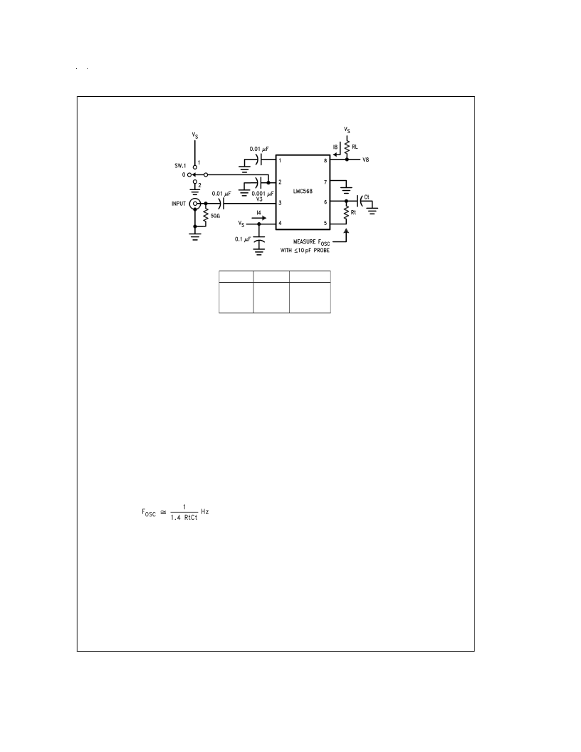
Test Circuit
RtCt
#
1
#
2
#
3
Rt
Ct
100k
10k
5.1k
300 pF
300 pF
62 pF
Notes to Typical Application
SUPPLY DECOUPLING
The decoupling of supply pin 4 becomes more critical at high
supply voltages with high operating frequencies, requiring
C4 to be placed as close to possible to pin 4.Also, due to pin
voltages tracking supply, a large C4 is necessary for low fre-
quency PSRR.
OSCILLATOR TIMING COMPONENTS
The voltage-controlled oscillator (VCO) on the LMC568 must
be set up to run at twice the frequency of the input signal.
The components shown in the typical application are for F
= 200 kHz (100 kHz input frequency). For operation at lower
frequencies, increase the capacitor value; for higher fre-
quencies proportionally reduce the resistor values.
If low distortion is not a requirement, the series diode/resistor
between pins 6 and 5 may be omitted. This will reduce VCO
supply dependence and increase V
by approximately 2 dB
with THD=2% typical. The center frequency as a function of
Rt and Ct is given by:
To allow for I.C. and component value tolerences, the oscil-
lator timing components will require a trim. This is generally
accomplished by using a variable resistor as part of Rt, al-
though Ct could also be padded. The amount of initial fre-
quency variation due to the LMC568 itself is given in the
electrical specifications; the total trim range must also ac-
commodate the tolerances of Rt and Ct.
INPUT PIN
The input pin 3 is internally ground-referenced with a nomi-
nal 40 k
resistor. Signals that are centered on 0V may be
directly coupled to pin 3; however, any d.c. potential must be
isolated via C3.
OUTPUT TAKEOFF
The output signal is taken off the loop filter at pin 2. Pin 2 is
the combined output of the phase detector and control input
of the VCO for the phase-locked loop (PLL). The nominal pin
2 source resistance is 80 k
, requiring the use of an external
buffer transistor to drive nominal loads.
For small values of C2, the PLL will have a fast acquisition
time and the pull-in range will be set by the built-in VCO fre-
quency stops, which also determine the largest detection
bandwidth (LDBW). Increasing C2 results in improved noise
immunity at the expense of acquisition time, and the pull-in
range will become narrower than the LDBW. However, the
maximum hold-in range will always equal the LDBW. The 2
kHz de-emphasis pole shown may be modified or omitted as
required by the application.
CARRIER DETECT
Pin 1 is the output of a negative-going amplitude detector
which has a nominal 0 signal output of 7/9 V
. The output at
pin 8 is an N-channel FET switch to ground which is acti-
vated when the PLL is locked and the input is of sufficient
amplitude to cause pin 1 to fall below 2/3 V
. The carrier de-
tect threshold is internally set to 26 mVrms typical on a 5V
supply.
Capacitor C1 in conjunction with the nominal 40 k
pin 1 in-
ternal resistance forms the output filter. The size of C1 is a
tradeoff between slew rate and carrier ripple at the output
comparator. Optional resistor R
increases the hysteresis in
the pin 8 output for applications such as audio mute control.
The minimum allowable value for R
H
is 330 k
.
DS009135-3
www.national.com
3
相關(guān)PDF資料 |
PDF描述 |
|---|---|
| LMC568CM | Low Power Phase-Locked Loop |
| LMC568CN | Low Power Phase-Locked Loop |
| LMC6009 | 9 Channel Buffer Amplifier for TFT-LCD |
| LMC6009MT | 9 Channel Buffer Amplifier for TFT-LCD |
| LMC6009MTX | 9 Channel Buffer Amplifier for TFT-LCD |
相關(guān)代理商/技術(shù)參數(shù) |
參數(shù)描述 |
|---|---|
| LMC568CM | 功能描述:鎖相環(huán) - PLL RoHS:否 制造商:Silicon Labs 類型:PLL Clock Multiplier 電路數(shù)量:1 最大輸入頻率:710 MHz 最小輸入頻率:0.002 MHz 輸出頻率范圍:0.002 MHz to 808 MHz 電源電壓-最大:3.63 V 電源電壓-最小:1.71 V 最大工作溫度:+ 85 C 最小工作溫度:- 40 C 封裝 / 箱體:QFN-36 封裝:Tray |
| LMC568CM NOPB | 制造商:National Semiconductor 功能描述:PLL Single Up to 0.5MHz 8-Pin SOIC N Rail |
| LMC568CM/NOPB | 功能描述:鎖相環(huán) - PLL RoHS:否 制造商:Silicon Labs 類型:PLL Clock Multiplier 電路數(shù)量:1 最大輸入頻率:710 MHz 最小輸入頻率:0.002 MHz 輸出頻率范圍:0.002 MHz to 808 MHz 電源電壓-最大:3.63 V 電源電壓-最小:1.71 V 最大工作溫度:+ 85 C 最小工作溫度:- 40 C 封裝 / 箱體:QFN-36 封裝:Tray |
| LMC568CMX | 功能描述:鎖相環(huán) - PLL RoHS:否 制造商:Silicon Labs 類型:PLL Clock Multiplier 電路數(shù)量:1 最大輸入頻率:710 MHz 最小輸入頻率:0.002 MHz 輸出頻率范圍:0.002 MHz to 808 MHz 電源電壓-最大:3.63 V 電源電壓-最小:1.71 V 最大工作溫度:+ 85 C 最小工作溫度:- 40 C 封裝 / 箱體:QFN-36 封裝:Tray |
| LMC568CMX/NOPB | 功能描述:鎖相環(huán) - PLL RoHS:否 制造商:Silicon Labs 類型:PLL Clock Multiplier 電路數(shù)量:1 最大輸入頻率:710 MHz 最小輸入頻率:0.002 MHz 輸出頻率范圍:0.002 MHz to 808 MHz 電源電壓-最大:3.63 V 電源電壓-最小:1.71 V 最大工作溫度:+ 85 C 最小工作溫度:- 40 C 封裝 / 箱體:QFN-36 封裝:Tray |
發(fā)布緊急采購,3分鐘左右您將得到回復。