- 您現(xiàn)在的位置:買賣IC網(wǎng) > PDF目錄358902 > LO5SMTPG4-B0G-A2 (Cree, Inc.) 5-mm Oval LED PDF資料下載
參數(shù)資料
| 型號(hào): | LO5SMTPG4-B0G-A2 |
| 廠商: | Cree, Inc. |
| 英文描述: | 5-mm Oval LED |
| 中文描述: | 5毫米橢圓形發(fā)光二極管 |
| 文件頁(yè)數(shù): | 3/5頁(yè) |
| 文件大?。?/td> | 306K |
| 代理商: | LO5SMTPG4-B0G-A2 |

Copyright 2007 Cree, Inc. All rights reserved. The information in this document is subject to change without notice. Cree and the
Cree logo are registered trademarks of Cree, Inc.
4/4 Format #: COTCO-D-074 REV.4
CLD-CT.000
Cree, Inc.
4600 Silicon Drive
Durham, NC 27703
USA Tel: +1.919.313.5300
Graphs
Document No. SPE/LO5SMTPG4-B0G-A2
Rev. No.
01
G
G
r
r
a
a
p
p
h
h
s
s
Ir(uA)
800
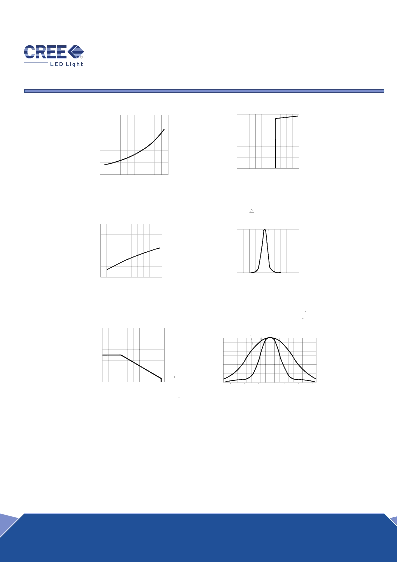
FIG.6 FAR FIELD PATTERN
FIG.4 RELATIVE LUMINOUS INTENSITY VS.
WAVELENGTH.
FIG.2 REVERSE CURRENT VS.
REVERSE VOLTAGE.
I (RELATIVE LUMINOUS INTENSITY)
100%
H-H : 110
V-V : 50
60
Domi WL= 525nm
5.0
3.0
2.0
1.0
0.0
50
40
30
10
20
0
4.0
FIG.3 RELATIVE LUMINOUS INTENSITY VS.
FORWARD CURRENT.
FIG.5 MAXIMUM FORWARD DC CURRENT VS
AMBIENT TEMPERATURE (Tjmax=105 C)
20.0
0.0
40.0
60.0
Ta( C)
100.0
80.0
-90
-60
-30
0
30
IF(mA)
0.0
20.0 40.0 60.0
If(mA)
80.0
100.0
H-H
50% Power Angle :
V-V
0
50%
0%
300
25%
75%
600
400
500
700
100.0
60.0
40.0
80.0
0.0
FORWARD VOLTAGE.
20.0
FIG.1 FORWARD CURRENT VS.
Vf(V)
If (mA)
Half Power WL=38nm
-40
-50
Vr(V)
-20
-10
-30
90
0%
20%
40%
100%
60%
80%
Ie(%)
WL(nm)
-50.0
-30.0
-40.0
0
-10.0
-20.0
0.0
3.0
3.4
3.8
4.2
4.6
5.0
Items
Signatures
Date
Revision History
Prepared by
LiuZM
2005-02-24
Rev. No
Date
Change Description
Checked by
MaJF
2005-02-24
Approved by
David
2005-02-24
ECN#
ECN-H20050055
Data is subject to change without prior notice; please refer to COTCO Website for the latest version.
Copyright@2002
Cotco International Ltd.
相關(guān)PDF資料 |
PDF描述 |
|---|---|
| LO5SMTWN1-B0G-A1 | 5-mm Oval LED |
| LO5SMTYL4-B0G-A | 5-mm Oval LED |
| LOA670-HK | SIDELED |
| LOA670-J | SIDELED |
| LOA670-JM | SIDELED |
相關(guān)代理商/技術(shù)參數(shù) |
參數(shù)描述 |
|---|---|
| LO5SMTWN1-B0G-A1 | 制造商:CREE 制造商全稱:Cree, Inc 功能描述:5-mm Oval LED |
| LO5SMTYL4-B0G-A | 制造商:CREE 制造商全稱:Cree, Inc 功能描述:5-mm Oval LED |
| LO5SMUHR4-B0G-A3 | 制造商:Cree 功能描述: |
| LO6 | 制造商:HellermannTyton 功能描述: |
| LO600Z | 制造商:SEOUL 制造商全稱:Seoul Semiconductor 功能描述:GREEN OVAL LAMP LED |
發(fā)布緊急采購(gòu),3分鐘左右您將得到回復(fù)。