- 您現(xiàn)在的位置:買賣IC網(wǎng) > PDF目錄367588 > LS4000 100 Watt AC-DC Converters with PFC PDF資料下載
參數(shù)資料
| 型號: | LS4000 |
| 英文描述: | 100 Watt AC-DC Converters with PFC |
| 中文描述: | 100瓦交直流轉(zhuǎn)換器的功率因數(shù)校正 |
| 文件頁數(shù): | 22/27頁 |
| 文件大小: | 599K |
| 代理商: | LS4000 |
第1頁第2頁第3頁第4頁第5頁第6頁第7頁第8頁第9頁第10頁第11頁第12頁第13頁第14頁第15頁第16頁第17頁第18頁第19頁第20頁第21頁當前第22頁第23頁第24頁第25頁第26頁第27頁

Cassette Style
100 Watt AC-DC Converters
S Series PFC
Edition 01/01.2001
22/27
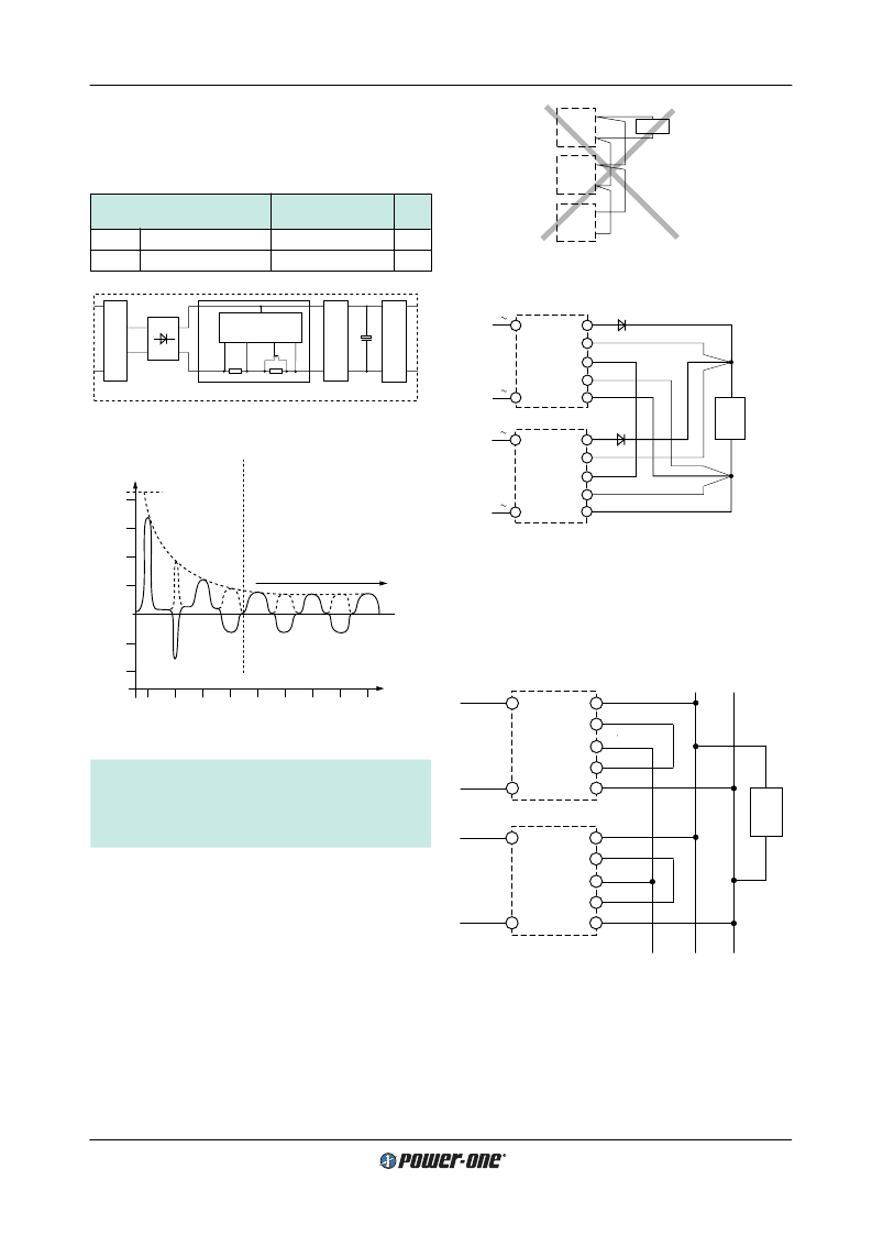
Fig. 34
Paralleling of single output units using option T with the
sense lines connected at the load
Load
max. 5 units in parallel connection
+
–
Power bus
Module
Vo2
–
Vo2+
Vo1
–
Vo1+
T
Module
Vo2
–
Vo2+
Vo1
–
Vo1+
T
11037
Load
1
1
1
2
2
3
3
LS 4000
S+
T
Vo+
Vo
–
S
–
N
P
LS 4000
N
P
S+
T
Vo+
Vo
–
S
–
1
max. 5 units connected in parallel
1
Leads should have equal length and cross sections and should
run in the same cable loom.
2
Diodes recommended in redundant operation only
3
DC common point
11011
Fig. 35
Paralleling of double output units using option T with
Power bus.
E Inrush Current Limitation
The converters may be supplemented by an electronic cir-
cuit (option E, replacing the standard built-in NTC) to
achieve an enhanced inrush current limiting function.
Table 17: Inrush current characteristics with option E
Characteristics
U
i
= 230 V AC
LS
Unit
typ
max
I
inr p
Peak inrush current
–
25.3
A
t
inr
Inrush current duration
35
50
ms
15
I
i
[A]
10
5
0
–
5
–
10
0
20
40
60
80
t [ms]
t
inr
Capacitor C
i
fully charged
Normal operation
(FET fully conducting)
20
10
50
70
30
11002
Fig. 32
Inrush current with option E, U
i
= 230 V AC, P
o
= P
o nom
Precaution:
Subsequent switch-on cycles at start-up are limited to
max. 10 cycles during the
fi
rst 20 seconds (cold unit)
and at continuing on/off (T
C
= 95
°
C) max. 1 cycle every
8 sec.
Vo+
Vo
–
Vo+
Vo
–
Load
Vo+
Vo
–
11003
I
Control
C
FET
C
i
R
I
R
S
Rectifier
P
1
Fig. 31
Option E block diagram
T Current Sharing
This option ensures that the output currents are approxi-
mately shared between all paralleled modules and in-
creases system reliability. To use this facility, simply inter-
connect the T pins of all modules and make sure, that
pin 14, the S
–
pin (S 4000) or the Vo1
–
pins (S 5000) are
also connected together. The load leads should have equal
length and cross section to ensure equal voltage drops. Not
more than 5 units should be connected in parallel. If output
voltage adjustment is requested we strongly recommend to
use the R-input instead of option P, as with option P the re-
quired setting accuracy is dif
fi
cult to achieve. The output
voltages must be individually set prior to paralleling to
within a tolerance of 1...2% or the R pins should be con-
nected together.
Fig. 33
An example of poor wiring for connection in parallel
相關PDF資料 |
PDF描述 |
|---|---|
| LS5320-7R | 100 Watt AC-DC Converters with PFC |
| LS4001-7R | 100 Watt AC-DC Converters with PFC |
| LS4301-7R | 100 Watt AC-DC Converters with PFC |
| LS5540-7R | 100 Watt AC-DC Converters with PFC |
| LS5660-7R | 100 Watt AC-DC Converters with PFC |
相關代理商/技術(shù)參數(shù) |
參數(shù)描述 |
|---|---|
| LS4001-7ER | 制造商:Power-One 功能描述: |
| LS4001-7R | 功能描述:線性和開關式電源 Euro-Cassette 100W (5.1V) RoHS:否 制造商:TDK-Lambda 產(chǎn)品:Switching Supplies 開放式框架/封閉式:Enclosed 輸出功率額定值:800 W 輸入電壓:85 VAC to 265 VAC 輸出端數(shù)量:1 輸出電壓(通道 1):20 V 輸出電流(通道 1):40 A 商用/醫(yī)用: 輸出電壓(通道 2): 輸出電流(通道 2): 安裝風格:Rack 長度: 寬度: 高度: |
| LS4001-9ER | 制造商:Power-One 功能描述:ACDC - Bulk |
| LS40077-003 | 制造商:MASTER.SPEC. 功能描述:LS40077-003 制造商:MASTER/- 功能描述:LS40077-003 |
| LS-400A | 功能描述:十進盒 Inductance RoHS:否 制造商:IET Labs 產(chǎn)品:Decade Resistance Boxes 電阻范圍:0 Ohms to 9999999 Ohms 準確性:+/- 1 % |
發(fā)布緊急采購,3分鐘左右您將得到回復。