- 您現(xiàn)在的位置:買賣IC網(wǎng) > PDF目錄377664 > LS7232ND (LSI Corporation) TOUCH CONTROL LAMP DIMMER PDF資料下載
參數(shù)資料
| 型號: | LS7232ND |
| 廠商: | LSI Corporation |
| 英文描述: | TOUCH CONTROL LAMP DIMMER |
| 中文描述: | 觸摸式控制燈調(diào)光器 |
| 文件頁數(shù): | 4/5頁 |
| 文件大小: | 48K |
| 代理商: | LS7232ND |
P
115VAC
OR
220VAC
N
LOAD
C1
T
L
C2
R1
R2
A
B
R8
R3
C5
D1
1
2
3
4
8
7
V
DD
6
EXT SENS
5
R4
C3
C4
TRIG
V
SS
MODE CAP SYNC
+
-
SEE NOTE 4
LS7232ND
R6
R5
SEE NOTE 3
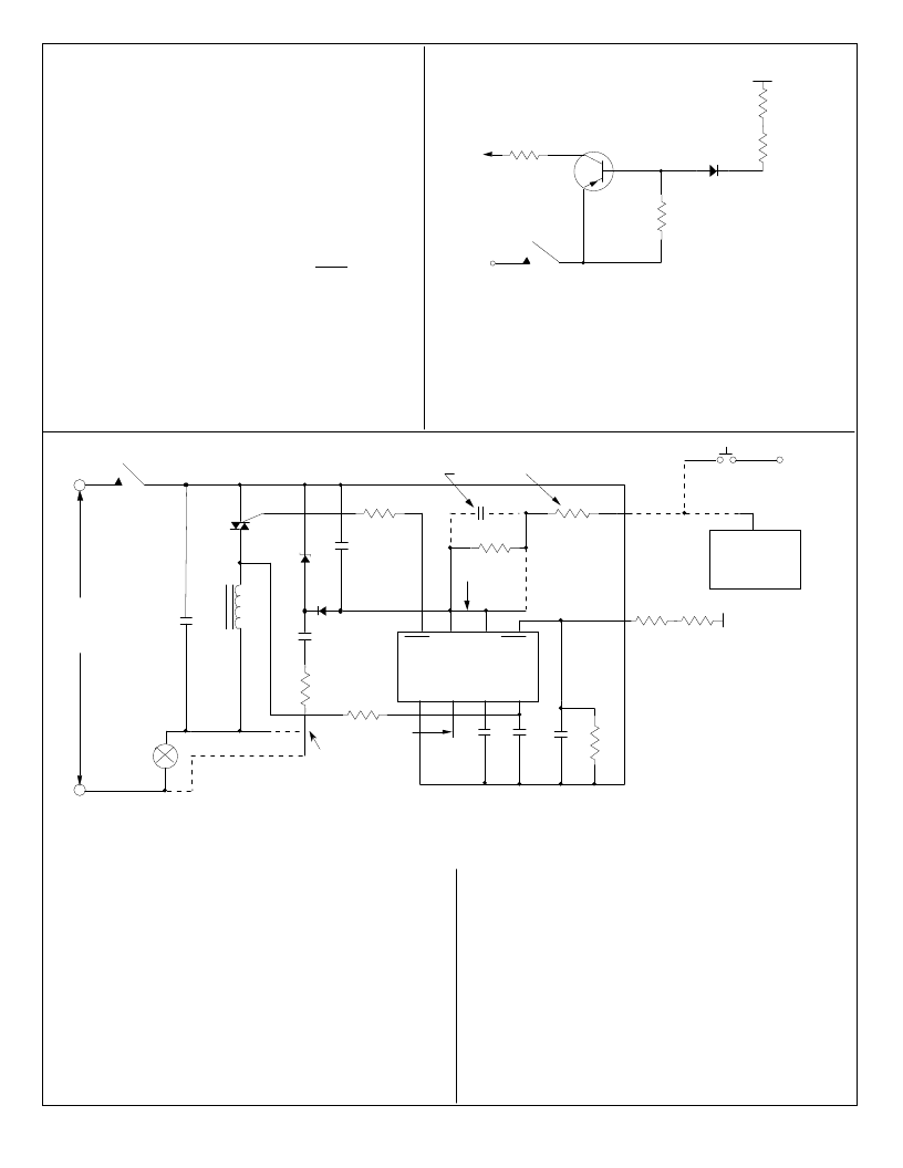
FIGURE 5. A Typical Lamp Dimmer
G
Z
ELECTRONIC
EXTENSION
(FIG. 6)
EXTN
P
C7
SEE NOTE 5
SEE NOTE 2
R7
C6
NOTES
1) All circuits connected by broken lines are optional.
2) C7 is used only with electronic extension and R7 is used only with mechanical switch.
3) See I/O Description for MODE (Pin 2)
4) Use Connection A when Neutral is not available. Use Connection B when Neutral is available.
5) Connection between Pin 6 & Pin 7 should be broken when EXT is used.
TOUCH
PLATE
MT2
MT1
APPLICATION EXAMPLE:
A typical implementation of a lamp dimmer circuit is shown
in Fig. 5. Here the brightness of the lamp is set by touching
the Touch Plate. The functions of different components are
as follows:
R1, C2 and C5.
R2 and C4 generate the filtered signal for the SYNC
input for synchronizing the internal PLL with the line
frequency.
R3 and C7 act as a filter circuit for the electronic
extension. If extensions are not used, the EXT input
(Pin 6) should be tied to V
DD
(Pin 7).
R4, R5, R6 set up the sensitivity of the SENS input.
C6 provides noise filtering.
C3 is the filter capacitor for the internal PLL.
R8 provides current limiting and isolation between the
chip output and the triac gate.
C1 and L are RF filter circuits.
The 15V DC supply for the chip is provided by Z, D1,
In the case of momentary power failure, the circuit state
remains unchanged for a period of up to 1 sec. For longer
power interruptions, the output is shut off.
C1 = 0.15μF, 200V
C2 = 0.33μF, 200V
C3 = 0.047μF, 25V
C4 = 470pF, 25V
C5 = 47μF, 25V
C6 = 680pF, 25V
C7 = 0.1μF, 25V
R1 = 270
, 1W
R2 = 1.5M
, 1/4W
R3 = 1.5M
, 1/4W
R4 = 1M
to 5M
, 1/4W
(Select for sensitivity)
R5, R6 = 2.7M
, 1/4W
R7 = 150k
, 1/4W
R8 = 100
, 1/4W
D1 = IN4148
Z = 15V, 1W (Zener)
T = Q4006L4 Triac (Typical)
L = 100μH (RFI Filter)
(1)
For Connection A. Use 0.22μF for Connection B.
(2)
For Connection A. Use 1/4W for Connection B.
C1 = 0.15μF, 400V
C2 = 0.22μF, 400V
C3 = 0.047μF, 25V
C4 = 470pF, 25V
C5 = 47μF, 25V
C6 = 680pF, 25V
C7 = 0.1μF, 25V
R1 = 1k
, 2W
R2 = 1.5M
, 1/4W
R3 = 1.5M
, 1/4W
R4 = 1M
to 5M
, 1/4W
(Select for sensitivity)
R5, R6 = 4.7M
, 1/4W
R7 = 150k
, 1/4W
R8 = 100
, 1/4W
D1 = 1N4148
Z = 15V, 1W (Zener)
T = Q5004L4 Triac (Typical)
L = 200μH (RFI Filter)
(3)
For Connection A. Use 0.1μF for Connection B.
(4)
For Connection A. Use 1/4W for Connection B
.
(1)
115V
220V
(2)
(3)
(4)
EXTN
2K
,1/4W
IN914
TOUCH PLATE
*R
200K
,1/4W
MPS8599
FIGURE 6. ELECTRONIC EXTENSION
*R
P
*R
= 2M
,1/4W for 115VAC
*R
= 3.6M
,1/4W for 220VAC
EXTENSIONS:
All switching and dimming functions can be implemented by utilizing the
EXT input. This can be done by either a pushbutton switch or the elec-
tronic switch in conjunction with a Touch Plate, shown in Figure 6.
When the plate is touched, a logic high level is generated at the EXT
input of the IC for both half- cycles of the line frequency. (See Figure 5)
7232ND-012703-4
相關PDF資料 |
PDF描述 |
|---|---|
| LS7232NT | PROXIMITY/TOUCH CONTROL HALOGEN LAMP DIMMER |
| LS7237 | TOUCH CONTROL LAMP STEP DIMMER |
| LS7260 | BRUSHLESS DC MOTOR COMMUTATOR/CONTROLLER |
| LS7262 | BRUSHLESS DC MOTOR COMMUTATOR/CONTROLLER |
| LS7310 | AC POWER CONTROLLERS |
相關代理商/技術(shù)參數(shù) |
參數(shù)描述 |
|---|---|
| LS7232NT | 制造商:LSI 制造商全稱:LSI 功能描述:PROXIMITY/TOUCH CONTROL HALOGEN LAMP DIMMER |
| LS7232NT-S | 制造商:未知廠家 制造商全稱:未知廠家 功能描述:Industrial Control IC |
| LS7232-S | 制造商:未知廠家 制造商全稱:未知廠家 功能描述:Analog Miscellaneous |
| LS7233 | 制造商:LSI 制造商全稱:LSI 功能描述:TOUCH CONTROL LAMP DIMMER |
| LS7233-S | 制造商:未知廠家 制造商全稱:未知廠家 功能描述:Analog Miscellaneous |
發(fā)布緊急采購,3分鐘左右您將得到回復。