- 您現(xiàn)在的位置:買(mǎi)賣IC網(wǎng) > PDF目錄377702 > LT1460 (Linear Technology Corporation) 2.5V Reference PDF資料下載
參數(shù)資料
| 型號(hào): | LT1460 |
| 廠商: | Linear Technology Corporation |
| 英文描述: | 2.5V Reference |
| 中文描述: | 2.5V參考 |
| 文件頁(yè)數(shù): | 7/12頁(yè) |
| 文件大?。?/td> | 287K |
| 代理商: | LT1460 |
7
LT1460-10
I
OUT
0
100
μ
A
10mA
20mA
LT1460AC
0.145%
0.180%
0.325%
0.425%
LT1460BI
0.225%
0.260%
0.405%
N/A
LT1460CC
0.205%
0.240%
0.385%
0.485%
LT1460DC
0.240%
0.275%
0.420%
0.520%
LT1460EI
0.375%
0.410%
0.555%
N/A
LT1460FC
0.325%
0.360%
0.505%
0.605%
LT1460GC
0.425%
0.460%
0.605%
0.705%
LT1460GI
0.562%
0.597%
0.742%
N/A
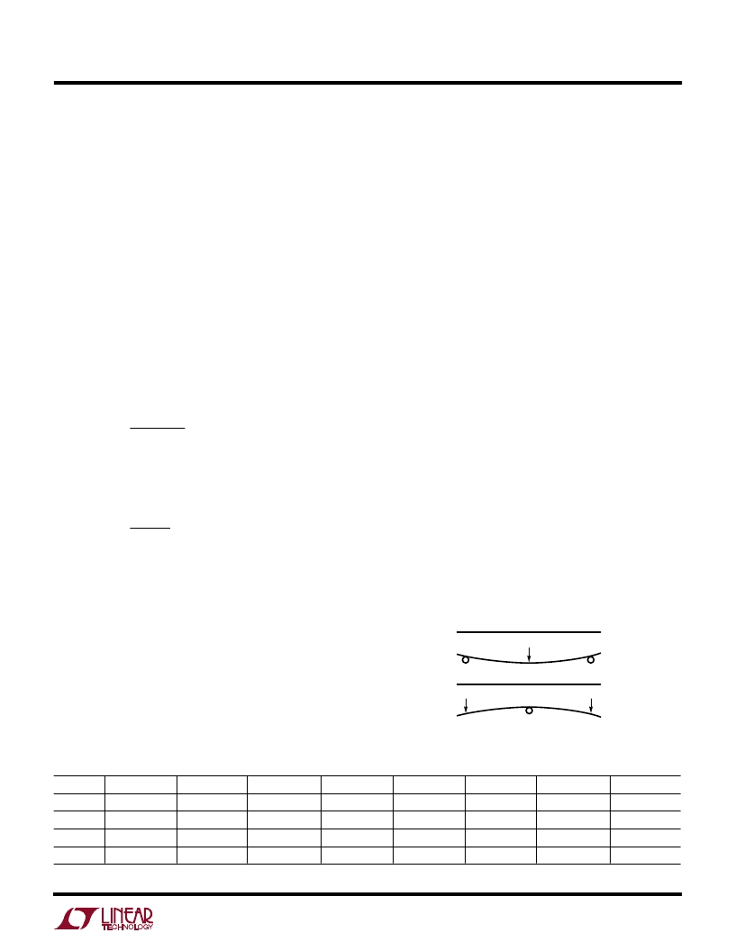
Figure 6. Flexure Numbers
for instance) can shift the output voltage and mask the true
temperature coefficient of a reference. In addition, the
mechanical stress of being soldered into a PC board can
cause the output voltage to shift from its ideal value.
Surface mount voltage references (MS8 and S8) are the
most susceptible to PC board stress because of the small
amount of plastic used to hold the lead frame.
A simple way to improve the stress-related shifts is to
mount the reference near the short edge of the PC board,
or in a corner. The board edge acts as a stress boundary,
or a region where the flexure of the board is minimum. The
package should always be mounted so that the leads
absorb the stress and not the package. The package is
generally aligned with the leads parallel to the long side of
the PC board as shown in Figure 7a.
A qualitative technique to evaluate the effect of stress on
voltage references is to solder the part into a PC board and
deform the board a fixed amount as shown in Figure 6. The
flexure #1 represents no displacement, flexure #2 is
concave movement, flexure #3 is relaxation to no dis-
placement and finally, flexure #4 is a convex movement.
This motion is repeated for a number of cycles and the
relative output deviation is noted. The result shown in
Figure 7a is for two LT1460S8-10s mounted vertically and
Figure 7b is for two LT1460S8-10s mounted horizontally.
The parts oriented in Figure 7a impart less stress into the
package because stress is absorbed in the leads. Figures
7a and 7b show the deviation to be between 500
μ
V and
1
2
3
4
1460-10 F06
Output Accuracy
Like all references, either series or shunt, the error budget
of the LT1460-10 is made up of primarily three compo-
nents: initial accuracy, temperature coefficient and load
regulation. Line regulation is neglected because it typically
contributes only 30ppm/V, or 300
μ
V for a 1V input change.
The LT1460-10 typically shifts less than 0.01% when
soldered into a PCB, so this is also neglected (see PC
Board Layout section). The output errors are calculated as
follows for a 100
μ
A load and 0
°
C to 70
°
C temperature
range:
LT1460AC
Initial accuracy = 0.075%
For I
O
= 100
μ
A,
V
ppm
mA
mA
V
mV
OUT
=
(
)(
)
=
3500
0 1
.
10
3 5
.
which is 0.035%.
For temperature 0
°
C to 70
°
C the maximum
T = 70
°
C,
V
ppm
C
°
C
V
mV
7
OUT
=
°
(
)(
)
=
10
70
10
which is 0.07%.
Total worst-case output error is:
0.075% + 0.035% + 0.070% = 0.180%.
Table 1 gives worst-case accuracy for the LT1460AC, CC,
DC, FC, GC from 0
°
C to 70
°
C and the LT1460BI, EI, GI
from –40
°
C to 85
°
C.
PC Board Layout
In 13- to 16-bit systems where initial accuracy and tem-
perature coefficient calibrations have been done, the
mechanical and thermal stress on a PC board (in a cardcage
APPLICATIO
S I
FOR
ATIO
U
W
U
U
相關(guān)PDF資料 |
PDF描述 |
|---|---|
| LT1460S3-SOT-23 | Family of Micropower Series References in SOT-23 |
| LT1460-2.5 | Micropower Precision Series Reference |
| LT1460GIZ-10 | Micropower Precision Series Reference |
| LT1460GIZ-2.5 | Micropower Precision Series Reference |
| LT1460GIZ-5 | Micropower Precision Series Reference |
相關(guān)代理商/技術(shù)參數(shù) |
參數(shù)描述 |
|---|---|
| LT1460_10 | 制造商:LINER 制造商全稱:Linear Technology 功能描述:Micropower Precision Series Reference Family |
| LT1460-10 | 制造商:LINER 制造商全稱:Linear Technology 功能描述:Micropower Precision Series Reference |
| LT1460-2.5 | 制造商:LINER 制造商全稱:Linear Technology 功能描述:Micropower Precision Series Reference |
| LT1460-5 | 制造商:LINER 制造商全稱:Linear Technology 功能描述:Micropower Precision Series Reference |
| LT1460A-10 | 制造商:LINER 制造商全稱:Linear Technology 功能描述:Dual Current Output 12-/14-/16-Bit SoftSpan DACs with Parallel I/O |
發(fā)布緊急采購(gòu),3分鐘左右您將得到回復(fù)。