- 您現(xiàn)在的位置:買賣IC網(wǎng) > PDF目錄377732 > LTC1143CS (LINEAR TECHNOLOGY CORP) Enclosures; Leaded Process Compatible:Yes; Peak Reflow Compatible (260 C):Yes RoHS Compliant: Yes PDF資料下載
參數(shù)資料
| 型號(hào): | LTC1143CS |
| 廠商: | LINEAR TECHNOLOGY CORP |
| 元件分類: | 穩(wěn)壓器 |
| 英文描述: | Enclosures; Leaded Process Compatible:Yes; Peak Reflow Compatible (260 C):Yes RoHS Compliant: Yes |
| 中文描述: | SWITCHING CONTROLLER, 400 kHz SWITCHING FREQ-MAX, PDSO16 |
| 封裝: | 0.150 INCH, PLASTIC, SO-16 |
| 文件頁(yè)數(shù): | 12/20頁(yè) |
| 文件大小: | 372K |
| 代理商: | LTC1143CS |
第1頁(yè)第2頁(yè)第3頁(yè)第4頁(yè)第5頁(yè)第6頁(yè)第7頁(yè)第8頁(yè)第9頁(yè)第10頁(yè)第11頁(yè)當(dāng)前第12頁(yè)第13頁(yè)第14頁(yè)第15頁(yè)第16頁(yè)第17頁(yè)第18頁(yè)第19頁(yè)第20頁(yè)
12
LTC1143/LTC1143L
LTC1143L-ADJ
APPLICATIO
S I
FOR
ATIO
U
Aluminum electrolytic and dry tantalum capacitors are
both available in surface mount configurations. In the case
of tantalum it is critical that the capacitors are surge tested
for use in switching power supplies. An excellent choice is
the AVX TPS series of surface mount tantalums, available
in case heights ranging from 2mm to 4mm. For example,
if 200
μ
F/10V is called for in an application requiring 3mm
height, (2) AVX 100
μ
F/10V (P/N TPSD 107M010) could be
used. Consult the manufacturer for other specific
recommendations.
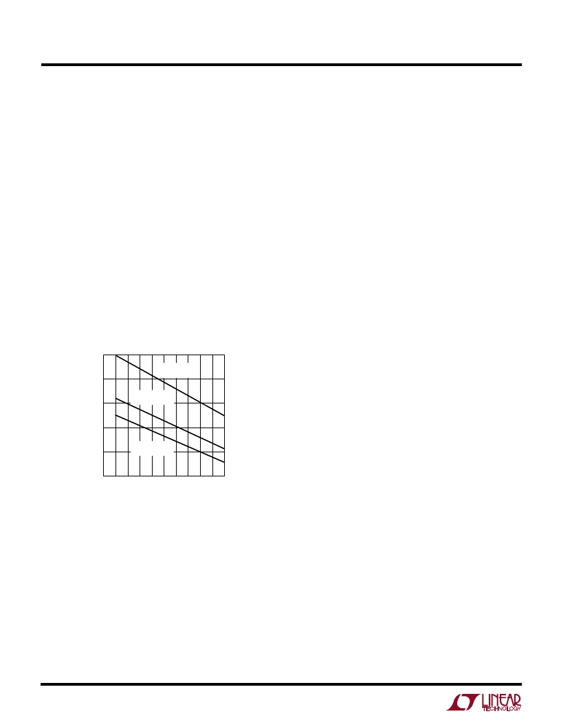
At low supply voltages a minimum
capacitance at C
OUT
is
needed to prevent an abnormal low frequency operating
mode (see Figure 4). When C
OUT
is made too small the
output ripple at low frequencies will be large enough to trip
the voltage comparator. This causes Burst Mode operation
to be activated when the LTC1143 series would normally
be in continuous operation. The output remains in
regulation at all times.
W
U
U
During this recovery time V
OUT
can be monitored for
overshoot or ringing which would indicate a stability
problem. The Pin 15(7) external components shown in the
Figure 1 circuit will prove adequate compensation for
most applications.
A second, more severe transient is caused by switching in
loads with large (>1
μ
F) supply bypass capacitors. The
discharged bypass capacitors are effectively put in parallel
with C
OUT
causing a rapid drop in V
OUT
. No regulator can
deliver enough current to prevent this problem if the load
switch resistance is low and it is driven quickly. The only
solution is to limit the rise time of the switch drive so that
the load rise time is limited to approximately 25 C
LOAD
.
Thus a 10
μ
F capacitor would require a 250
μ
s rise time,
limiting the charging current to about 200mA.
Efficiency Considerations
The percent efficiency of a switching regulator is equal to
the output power divided by the input power times 100%.
It is often useful to analyze individual losses to determine
what is limiting the efficiency and which change would
produce the most improvement. Percent efficiency can be
expressed as:
%Efficiency = 100% – (L1 + L2 + L3 + ...)
where L1, L2, etc. are the individual losses as a percentage
of input power. (For high efficiency circuits only small
errors are incurred by expressing losses as a percentage
of output power.)
Although all dissipative elements in the circuit produce
losses, four main sources usually account for most of the
losses in LTC1143 series circuits:
1) DC bias current
2) MOSFET gate charge current
3) I
2
R losses
4) Voltage drop of the Schottky diode.
1) The DC supply current is the current that flows into
V
IN
(Pin 13 and Pin 5) less the gate charge current. For
V
IN
= 10V the DC supply current for each section is 160
μ
A
for no load and increases proportionally with load up to
a constant 1.6mA after the LTC1143 series has entered
continuous mode. Because the DC bias current is
V
IN
– V
OUT
VOLTAGE (V)
0
C
O
μ
F
1000
800
600
400
200
0
4
1143 F04
1
2
3
5
L = 50
μ
H
R
SENSE
= 0.02
L = 25
μ
H
R
SENSE
= 0.02
L = 50
μ
H
R
SENSE
= 0.05
Figure 4. Minimum Value of C
OUT
Checking Transient Response
The regulator loop response can be checked by looking at
the load transient response. Switching regulators take
several cycles to respond to a step in DC (resistive) load
current. When a load step occurs, V
OUT
shifts by an
amount equal to
I
LOAD
×
ESR, where ESR is the effective
series resistance of C
OUT
.
I
LOAD
also begins to charge or
discharge C
OUT
until the regulator loop adapts to the
current change and returns V
OUT
to its steady-state value.
相關(guān)PDF資料 |
PDF描述 |
|---|---|
| LTC1143L-ADJ | RADIATION HARDENED HIGH EFFICIENCY, 5 AMP SWITCHING REGULATORS |
| LTC1143LCS-ADJ | RADIATION HARDENED HIGH EFFICIENCY, 5 AMP SWITCHING REGULATORS |
| LTC1143 | OCTAL BUS TRANSCEIVER O.C. 20-SO 0 to 70 |
| LTC1143L | RADIATION HARDENED HIGH EFFICIENCY, 5 AMP SWITCHING REGULATORS |
| LTC1143LCS | RADIATION HARDENED HIGH EFFICIENCY, 5 AMP SWITCHING REGULATORS |
相關(guān)代理商/技術(shù)參數(shù) |
參數(shù)描述 |
|---|---|
| LTC1143CS#PBF | 功能描述:IC REG CTRLR BUCK PWM CM 16-SOIC RoHS:是 類別:集成電路 (IC) >> PMIC - 穩(wěn)壓器 - DC DC 切換控制器 系列:- 標(biāo)準(zhǔn)包裝:2,500 系列:- PWM 型:電流模式 輸出數(shù):1 頻率 - 最大:500kHz 占空比:96% 電源電壓:4 V ~ 36 V 降壓:無(wú) 升壓:是 回掃:無(wú) 反相:無(wú) 倍增器:無(wú) 除法器:無(wú) Cuk:無(wú) 隔離:無(wú) 工作溫度:-40°C ~ 125°C 封裝/外殼:24-WQFN 裸露焊盤(pán) 包裝:帶卷 (TR) |
| LTC1143CS#TR | 功能描述:IC REG CTRLR BUCK PWM CM 16-SOIC RoHS:否 類別:集成電路 (IC) >> PMIC - 穩(wěn)壓器 - DC DC 切換控制器 系列:- 標(biāo)準(zhǔn)包裝:2,500 系列:- PWM 型:電流模式 輸出數(shù):1 頻率 - 最大:500kHz 占空比:96% 電源電壓:4 V ~ 36 V 降壓:無(wú) 升壓:是 回掃:無(wú) 反相:無(wú) 倍增器:無(wú) 除法器:無(wú) Cuk:無(wú) 隔離:無(wú) 工作溫度:-40°C ~ 125°C 封裝/外殼:24-WQFN 裸露焊盤(pán) 包裝:帶卷 (TR) |
| LTC1143CS#TRPBF | 功能描述:IC REG CTRLR BUCK PWM CM 16-SOIC RoHS:是 類別:集成電路 (IC) >> PMIC - 穩(wěn)壓器 - DC DC 切換控制器 系列:- 標(biāo)準(zhǔn)包裝:2,500 系列:- PWM 型:電流模式 輸出數(shù):1 頻率 - 最大:500kHz 占空比:96% 電源電壓:4 V ~ 36 V 降壓:無(wú) 升壓:是 回掃:無(wú) 反相:無(wú) 倍增器:無(wú) 除法器:無(wú) Cuk:無(wú) 隔離:無(wú) 工作溫度:-40°C ~ 125°C 封裝/外殼:24-WQFN 裸露焊盤(pán) 包裝:帶卷 (TR) |
| LTC1143L | 制造商:LINER 制造商全稱:Linear Technology 功能描述:Dual High Efficiency SO-16 Step-Down Switching Regulator Controllers |
| LTC1143L-ADJ | 制造商:LINER 制造商全稱:Linear Technology 功能描述:Dual High Efficiency SO-16 Step-Down Switching Regulator Controllers |
發(fā)布緊急采購(gòu),3分鐘左右您將得到回復(fù)。