- 您現在的位置:買賣IC網 > PDF目錄377774 > LTC3406B (Linear Technology Corporation) Dual DC/DC Converter with USB Power Manager and Li-Ion Battery Charger PDF資料下載
參數資料
| 型號: | LTC3406B |
| 廠商: | Linear Technology Corporation |
| 元件分類: | 基準電壓源/電流源 |
| 英文描述: | Dual DC/DC Converter with USB Power Manager and Li-Ion Battery Charger |
| 中文描述: | 雙DC / DC轉換器的USB電源管理器和鋰離子電池充電器 |
| 文件頁數: | 14/24頁 |
| 文件大小: | 516K |
| 代理商: | LTC3406B |
LTC3455
14
3455f
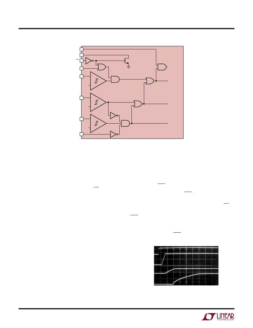
Figure 3. Turn-On Logic Diagram for LTC3455
APPLICATIU
W
U
U
Figure 4. Sequencing for Switcher 1 and 2 Outputs
Startup and Shutdown When USB or Wall Powered
Whenever USB or wall power is present (as sensed by the
USB and WALLFB pins), Switcher 1 and the battery
charger will always be enabled. If the LTC3455 is off and
external power is applied, both the charger and Switcher
1 will start independent of the state of the ON and PWRON
pins. This provides maximum battery run-time by always
allowing the battery to charge whenever external power is
available, and ensures that the microcontroller is always
alive when external power is available (this is important for
designs that utilize coulomb-counting or other battery
monitoring techniques). Switcher 2 starts only if ON2 is
also pulled high. Figure 3 shows the turn-on logic diagram
for the LTC3455.
Starting Switcher 2/Power Supply Sequencing
Switcher 2 can operate only when Switcher 1 is also
enabled and in regulation. The ON2 pin can be driven by a
logic signal for independent control of Switcher 2. If both
outputs always operate together, tie the ON2 pin to the
V
MAX
pin. This will enable Switcher 2 after the output of
Switcher 1 has reached 90% of its final value. This power-
up delay ensures proper supply sequencing and reduces
the peak battery current at startup. Figure 4 shows the
output sequencing when both switchers are enabled at
startup with the ON2 pin tied to V
MAX
. The turn-on of both
switchers is always delayed until the V
MAX
pin has reached
the V
BAT
pin voltage.
Reset Signal (RST)
A 200ms reset signal (the RST pin is pulled low) is
provided for proper initialization of a microcontroller when-
ever the LTC3455 is first turned on, either by the ON or
PWRON pins, or by the application of external power. The
RST signal is also pulled low whenever the LTC3455 is in
shutdown, ensuring no false starts for the microcontroller
as the output voltages are rising or collapsing. In the event
of a fault condition the RST pin will be pulled low.
6
9
SUSPEND
24
ON
23
19
ON2
PBSTAT
22
PWRON
V
BAT
3V
–
+
11
WALLFB
1.23V
–
+
8
USB
3.9V
–
+
USB POWER
CONTROLLER
ENABLED
CHARGER
ENABLED
SWITCHER 1
ENABLED
SWITCHER 2
ENABLED
LTC3455
3455 F03
PWRON/ON2
2V/DIV
V
2V/DIV
100
μ
s/DIV
3455 F04
V
OUT1
(1.8V)
2V/DIV
V
OUT2
(3.3V)
2V/DIV
相關PDF資料 |
PDF描述 |
|---|---|
| LTC3406ES5 | 1.5MHz, 600mA Synchronous Step-Down Regulator in ThinSOT |
| LTC3407 | Dual DC/DC Converter with USB Power Manager and Li-Ion Battery Charger |
| LTC3412 | Dual DC/DC Converter with USB Power Manager and Li-Ion Battery Charger |
| LTC3406ES5-1.5 | 1.5MHz, 600mA Synchronous Step-Down Regulator in ThinSOT |
| LTC3406ES5-1.8 | 1.5MHz, 600mA Synchronous Step-Down Regulator in ThinSOT |
相關代理商/技術參數 |
參數描述 |
|---|---|
| LTC3406B-1.2 | 制造商:LINER 制造商全稱:Linear Technology 功能描述:1.5MHz, 600mA Synchronous Step-Down Regulator in ThinSOT |
| LTC3406B-1.5 | 制造商:LINER 制造商全稱:Linear Technology 功能描述:1.5MHz, 600mA Synchronous Step-Down egulator in ThinSOT |
| LTC3406B-1.8 | 制造商:LINER 制造商全稱:Linear Technology 功能描述:1.5MHz, 600mA Synchronous Step-Down egulator in ThinSOT |
| LTC3406B-2 | 制造商:LINER 制造商全稱:Linear Technology 功能描述:2.25MHz, 600mA Synchronous Step-Down Regulator in ThinSOT |
| LTC3406B-2ES5 | 制造商:Linear Technology 功能描述:Conv DC-DC Single Step Down 2.5V to 5.5V 5-Pin TSOT-23 |
發(fā)布緊急采購,3分鐘左右您將得到回復。