- 您現(xiàn)在的位置:買賣IC網(wǎng) > PDF目錄39425 > LTC3547EDDB-1#PBF (LINEAR TECHNOLOGY CORP) 0.7 A DUAL SWITCHING CONTROLLER, 2700 kHz SWITCHING FREQ-MAX, PDSO8 PDF資料下載
參數(shù)資料
| 型號: | LTC3547EDDB-1#PBF |
| 廠商: | LINEAR TECHNOLOGY CORP |
| 元件分類: | 穩(wěn)壓器 |
| 英文描述: | 0.7 A DUAL SWITCHING CONTROLLER, 2700 kHz SWITCHING FREQ-MAX, PDSO8 |
| 封裝: | 3 X 2 MM, 0.75 MM HEIGHT, LEAD FREE, PLASTIC, M0-229WECD-1, DFN-8 |
| 文件頁數(shù): | 15/16頁 |
| 文件大小: | 296K |
| 代理商: | LTC3547EDDB-1#PBF |
LTC3547
8
3547fa
APPLICATIO S I FOR ATIO
WU
U
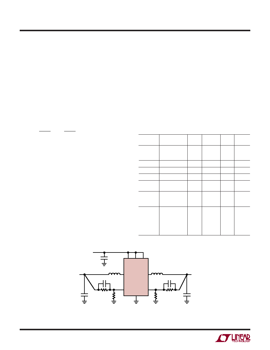
A general LTC3547 application circuit is shown in
Figure 1. External component selection is driven by the
load requirement, and begins with the selection of the
inductor L. Once the inductor is chosen, CIN and COUT
can be selected.
Inductor Selection
Although the inductor does not inuence the operat-
ing frequency, the inductor value has a direct effect on
ripple current. The inductor ripple current ΔIL decreases
with higher inductance and increases with higher VIN
or VOUT:
I
V
fL
V
L
OUT
O
OUT
IN
=
1
(1)
Accepting larger values of ΔIL allows the use of low
inductances, but results in higher output voltage ripple,
greater core losses, and lower output current capability.
A reasonable starting point for setting ripple current
is 40% of the maximum output load current. So, for a
300mA regulator, ΔIL = 120mA (40% of 300mA).
The inductor value will also have an effect on Burst Mode
operation. The transition to low current operation begins
when the peak inductor current falls below a level set by
the internal burst clamp. Lower inductor values result in
higher ripple current which causes the transition to occur
at lower load currents. This causes a dip in efciency in
the upper range of low current operation. Furthermore,
lower inductance values will cause the bursts to occur
with increased frequency.
Inductor Core Selection
Different core materials and shapes will change the
size/current and price/current relationship of an induc-
tor. Toroid or shielded pot cores in ferrite or permalloy
materials are small and do not radiate much energy, but
generally cost more than powdered iron core inductors
with similar electrical characteristics. The choice of which
style inductor to use often depends more on the price vs
size requirements, and any radiated eld/EMI requirements,
than on what the LTC3547 requires to operate. Table 1
shows some typical surface mount inductors that work
well in LTC3547 applications.
Figure 1. LTC3547 General Schematic
CF2
CF1
VIN
2.5V TO 5.5V
VOUT2
VOUT1
3547 F01
R3
R1
R4
L2
L1
R2
COUT2
C1
COUT1
VIN
RUN2
RUN1
LTC3547
VFB2
SW2
SW1
VFB1
GND
Table 1. Representative Surface Mount Inductors
MANU-
FACTURER
PART NUMBER
VALUE
MAX DC
CURRENT
DCR
HEIGHT
Taiyo Yuden
CB2016T2R2M
CB2012T2R2M
CB2016T3R3M
2.2H
3.3H
510mA
530mA
410mA
0.13Ω
0.33Ω
0.27Ω
1.6mm
1.25mm
1.6mm
Panasonic
ELT5KT4R7M
4.7H
950mA
0.2Ω
1.2mm
Sumida
CDRH2D18/LD
4.7H
630mA
0.086Ω
2mm
Murata
LQH32CN4R7M23
4.7H
450mA
0.2Ω
2mm
Taiyo Yuden
NR30102R2M
NR30104R7M
2.2H
4.7H
1100mA
750mA
0.1Ω
0.19Ω
1mm
FDK
FDKMIPF2520D
4.7H
3.3H
2.2H
1100mA
1200mA
1300mA
0.11Ω
0.1Ω
0.08Ω
1mm
TDK
VLF3010AT4R7-
MR70
VLF3010AT3R3-
MR87
VLF3010AT2R2-
M1RD
4.7H
3.3H
2.2H
700mA
870mA
1000mA
0.24Ω
0.17Ω
0.12Ω
1mm
相關(guān)PDF資料 |
PDF描述 |
|---|---|
| LTC3564EDCB#PBF | 2.5 A SWITCHING REGULATOR, 2700 kHz SWITCHING FREQ-MAX, PDSO6 |
| LTC3564IDCB#PBF | 2.5 A SWITCHING REGULATOR, 2700 kHz SWITCHING FREQ-MAX, PDSO6 |
| LTC3604IMSE#PBF | SWITCHING REGULATOR, PDSO16 |
| LTC3604IUD#TRPBF | SWITCHING REGULATOR, PQCC16 |
| LTC3604IUD#PBF | SWITCHING REGULATOR, PQCC16 |
相關(guān)代理商/技術(shù)參數(shù) |
參數(shù)描述 |
|---|---|
| LTC3548 | 制造商:LINER 制造商全稱:Linear Technology 功能描述:Dual Synchronous,400mA/800mA, 2.25MHz Step-Down DC/DC Regulator |
| LTC3548-1 | 制造商:LINER 制造商全稱:Linear Technology 功能描述:Dual Synchronous, Fixed Output 2.25MHz Step-Down DC/DC Regulator |
| LTC3548-2 | 制造商:LINER 制造商全稱:Linear Technology 功能描述:Dual Synchronous, Fixed/Adjustable Output, 2.25MHz Step-Down DC/DC Regulator |
| LTC3548A | 制造商:LINER 制造商全稱:Linear Technology 功能描述:Dual Synchronous 400mA/800mA, 2.25MHz Step-Down DC/DC Regulator |
| LTC3548AEDD | 制造商:LINER 制造商全稱:Linear Technology 功能描述:Dual Synchronous 400mA/800mA, 2.25MHz Step-Down DC/DC Regulator |
發(fā)布緊急采購,3分鐘左右您將得到回復(fù)。