- 您現(xiàn)在的位置:買賣IC網(wǎng) > PDF目錄358960 > LTW-2S3D7 (LITE-ON ELECTRONICS INC) Low power consumption, High efficiency, Versatile mounting on p.c. board or panel PDF資料下載
參數(shù)資料
| 型號: | LTW-2S3D7 |
| 廠商: | LITE-ON ELECTRONICS INC |
| 元件分類: | LED |
| 英文描述: | Low power consumption, High efficiency, Versatile mounting on p.c. board or panel |
| 中文描述: | T-1 3/4 SINGLE COLOR LED, WHITE, 5 mm |
| 文件頁數(shù): | 7/8頁 |
| 文件大小: | 196K |
| 代理商: | LTW-2S3D7 |
LITE-ON TECHNOLOGY CORPORATION
Property of Lite-On Only
CAUTIONS
1.
Application
The LEDs described here are intended to be used for ordinary electronic equipment (such as office equipment,
communication equipment and household applications). Consult Liteon’s Sales in advance for information on
applications in which exceptional reliability is required, particularly when the failure or malfunction of the
LEDs may directly jeopardize life or health (such as in aviation, transportation, traffic control equipment,
medical and life support systems and safety devices).
2. Storage
The storage ambient for the LEDs should not exceed 30°C temperature or 70% relative humidity. It is
recommended that LEDs out of their original packaging are used within three months.
For extended storage out of their original packaging, it is recommended that the LEDs be stored in a sealed
container with appropriate desiccant or in a dessicator with nitrogen ambient.
3. Cleaning
Use alcohol-based cleaning solvents such as isopropyl alcohol to clean the LEDs if necessary.
4. Lead Forming & Assembly
During lead forming, the leads should be bent at a point at least 3mm from the base of LED lens. Do not use
the base of the leadframe as a fulcrum during forming. Lead forming must be done before soldering at normal
temperature. During assembly on PCB, use minimum clinch force possible to avoid excessive mechanical stress
5. Soldering
When soldering, leave a minimum of 2mm clearance from the base of the lens to the soldering point.
Dipping the lens into the solder must be avoided.
Do not apply any external stress to the lead frame during soldering while the LED is at high temperature.
Recommended soldering condition:
Soldering iron
Wave soldering
Temperature
Soldering time
300°C Max.
3 sec. Max.
(one time only)
Pre-heat
Pre-heat time
Solder wave
Soldering time
100°C Max.
60 sec. Max.
260°C Max.
10 sec. Max.
Note: Excessive soldering temperature and/or time might result in deformation of the LED lens or catastrophic
failure of the LED. IR re-flow is not suitable process for through hole type LED lamp production.
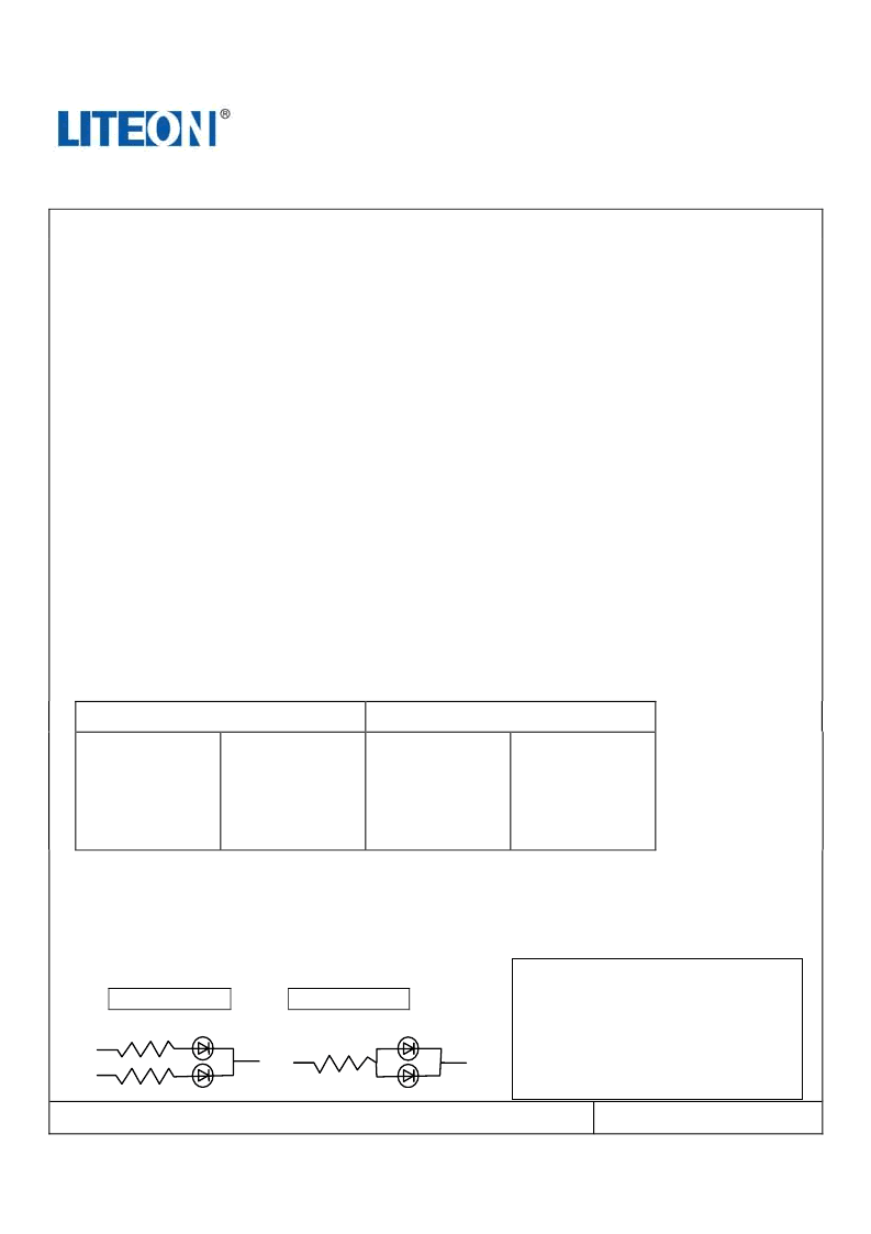
6. Drive Method
An LED is a current operated device, In order to ensure intensity uniformity on multiple LEDs connected in
parallel in an application; it is recommended that a current limiting resistor be incorporated in the drive circuit. In
series with each LED as shown in Circuit A below.
Circuit model A
Circuit model B
LED
LED
Part No. : LTW-2S3D7
Page : 7 of 8
BNS-OD-C131/A4
(A)
Recommended circuit.
(B)
The brightness of each LED might
appear different due to the differences
in the I-V characteristics of those
LEDs
相關(guān)PDF資料 |
PDF描述 |
|---|---|
| LTW-42NC5 | Low power consumption, High efficiency |
| LTW-670DS | LED |
| LU100Z | GREEN OVAL LAMP LED |
| LU241 | RED OVAL LAMP LED |
| LU5350 | TWO-COLOR, RED AND GREEN T1 LED LAMP |
相關(guān)代理商/技術(shù)參數(shù) |
參數(shù)描述 |
|---|---|
| LTW-2S3D7-012 | 制造商:LITEON 制造商全稱:Lite-On Technology Corporation 功能描述:Property of Lite-On Only |
| LTW-2S3D7-2 | 制造商:LITEON 制造商全稱:Lite-On Technology Corporation 功能描述:Property of Lite-On Only |
| LTW-2S3D7S | 制造商:LITEON 制造商全稱:Lite-On Technology Corporation 功能描述:Property of Lite-On Only |
| LTW2S3D8 | 制造商:Lite-On Semiconductor Corporation 功能描述: |
| LTW-2S3D8 | 功能描述:標(biāo)準(zhǔn)LED-通孔 White Water Clear 17000mcd 20mA RoHS:否 制造商:Vishay Semiconductors 照明顏色:Red 光強(qiáng)度:0.7 mcd 波長/色溫:615 nm 顯示角:45 deg 透鏡顏色/類型:Clear, Non-Diffused 正向電流:70 mA 正向電壓:1.83 V to 3.03 V LED 大小:2 mm 系列: 封裝:Tube |
發(fā)布緊急采購,3分鐘左右您將得到回復(fù)。