- 您現(xiàn)在的位置:買賣IC網(wǎng) > PDF目錄358960 > LU7790H2D1A (Sharp Corporation) Interface Add-on Board(接口擴(kuò)充卡) PDF資料下載
參數(shù)資料
| 型號(hào): | LU7790H2D1A |
| 廠商: | Sharp Corporation |
| 英文描述: | Interface Add-on Board(接口擴(kuò)充卡) |
| 中文描述: | 接口附加委員會(huì)(接口擴(kuò)充卡) |
| 文件頁數(shù): | 3/10頁 |
| 文件大?。?/td> | 172K |
| 代理商: | LU7790H2D1A |
Interface Add-on Board
LU7790H2D1A
Data Sheet
Page 3
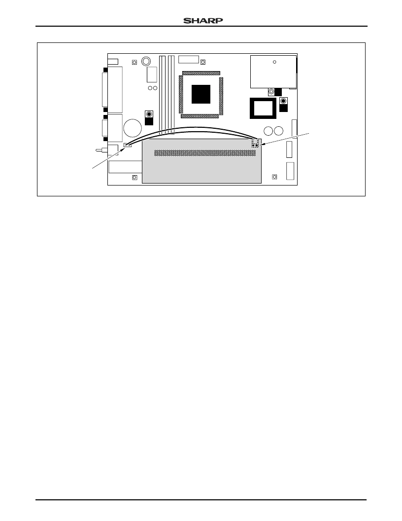
J6 and JP4 on the add-on board allow use of the
loud speaker driver provided on the LU77790H2AB0
evaluation board with an earphone or a loud speaker
with 3.5 mm mono audio jack.
J6 is directly and only connected to JP4. To use a
loud speaker or earphone with J6, a connection is
required between JP4 on the add-on board and U4 on
the evaluation board as shown in Figure 3.
This connection is only required if you want to use
an earphone or loud speaker with a 3.5 mm audio plug.
Please note that the cable required between U4 and
JP4 is not included with the add-on board.
FUNCTIONAL DESCRIPTION
Power Supply
The LU7790H2D1A is powered by the +5 V voltage
supplied by the LU7790H2AB0 evaluation board. The
+9 VDC to +12 VDC input voltage to the evaluation
board is used to power the backlight converter for the
LM5Q32 panel.
LCD Power Supply
The logic circuits of the LM5Q32 passive color panel
operate at 5 V and are powered directly from the +5 V
supplied by the evaluation board.
The logic circuits of the DMTN panels LM4Q30TA
and LM5H40TA operate at 3.3 V. The linear voltage
regulator U4 on the add-on board generates a 3.3 V
supply voltage for the DMTN panels.
The LU7790H2AB0 evaluation board generates a
negative supply voltage VEE- in the range of -20 V to
-25 V for the LM32P07 panel installed in the Evaluation
Unit (LU7790H2BK1). The board also contains circuitry
to enable VEE- only when the clock signals are supplied
to the LCD panel. This is a protective measure to pre-
vent a destructive DC build-up in the LCD panel when
the LCD controller is not operating properly, as could
happen during software debugging, for example.
To generate the positive voltage VEE+ in the range
of 13 V to 28 V required for the LM4Q30TA, LM5H40TA
and LM5Q32, the LU7790H2D1A board contains a
simple switching regulator, which is built around U6, L1
and D1.
Figure 3. Connecting J4 and JP4
LU7790H2D1A
7790H2-3
U4 PIN 1
JP4 PIN 1
相關(guān)PDF資料 |
PDF描述 |
|---|---|
| LU8500F0 | 8-bit Single-chip Microcomputer with built-in Flash Memory |
| LU8500F1 | 8-bit Single-chip Microcomputer with built-in Flash Memory |
| LU850425 | 8-bit Microcomputer for DSP Camera Systems |
| LUB1000 | PHOTODIODE BLUE 29.02MM SQ CER |
| LUB30243 | LUB30243 |
相關(guān)代理商/技術(shù)參數(shù) |
參數(shù)描述 |
|---|---|
| LU780Z | 制造商:SEOUL 制造商全稱:Seoul Semiconductor 功能描述:GREEN OVAL LAMP LED |
| LU781 | 制造商:SEOUL 制造商全稱:Seoul Semiconductor 功能描述:RED OVAL LAMP LED |
| LU78-5005 | 制造商:FLOWLINE 功能描述:Sensor, Ultrasonic, Level Switch, 24.6 ft Range, 95-250 VAC, 2 in NPT,EchoSwitch |
| LU78-5065 | 制造商:FLOWLINE 功能描述:EchoSwitch II Level Switch & Cont.; 8m (26.2'); 95-250 VAC; 1 IN G |
| LU790Z | 制造商:SEOUL 制造商全稱:Seoul Semiconductor 功能描述:GREEN OVAL LAMP LED |
發(fā)布緊急采購,3分鐘左右您將得到回復(fù)。