- 您現(xiàn)在的位置:買(mǎi)賣(mài)IC網(wǎng) > PDF目錄367613 > LUCL8560AP-D Top Entry Connector Hood; Enclosure Material:Aluminum Alloy; For Use With:C146 Rectangular Circular Connectors; Thread Size:PG 21; Connecting Termination:Screw; No. of Contacts:16; Operating Voltage:400V; Series:C-146 RoHS Compliant: Yes PDF資料下載
參數(shù)資料
| 型號(hào): | LUCL8560AP-D |
| 元件分類: | 圓形連接器 |
| 英文描述: | Top Entry Connector Hood; Enclosure Material:Aluminum Alloy; For Use With:C146 Rectangular Circular Connectors; Thread Size:PG 21; Connecting Termination:Screw; No. of Contacts:16; Operating Voltage:400V; Series:C-146 RoHS Compliant: Yes |
| 中文描述: | 低功耗振鈴用戶接口 |
| 文件頁(yè)數(shù): | 33/46頁(yè) |
| 文件大?。?/td> | 842K |
| 代理商: | LUCL8560AP-D |
第1頁(yè)第2頁(yè)第3頁(yè)第4頁(yè)第5頁(yè)第6頁(yè)第7頁(yè)第8頁(yè)第9頁(yè)第10頁(yè)第11頁(yè)第12頁(yè)第13頁(yè)第14頁(yè)第15頁(yè)第16頁(yè)第17頁(yè)第18頁(yè)第19頁(yè)第20頁(yè)第21頁(yè)第22頁(yè)第23頁(yè)第24頁(yè)第25頁(yè)第26頁(yè)第27頁(yè)第28頁(yè)第29頁(yè)第30頁(yè)第31頁(yè)第32頁(yè)當(dāng)前第33頁(yè)第34頁(yè)第35頁(yè)第36頁(yè)第37頁(yè)第38頁(yè)第39頁(yè)第40頁(yè)第41頁(yè)第42頁(yè)第43頁(yè)第44頁(yè)第45頁(yè)第46頁(yè)

Lucent Technologies Inc.
33
Data Sheet
April 2000
L8560 Low-Power SLIC with Ringing
Applications
(continued)
Design Considerations
Unbalanced Bused Ring Signal Application
The L8560 SLIC can also be used in the standard bat-
tery-backed, unbalanced ringing application. In this
case, the ring signal is generated by a central ring gen-
erator and is bused to individual tip/ring pairs. A ringing
relay is used during ringing to disconnect the SLIC
from, and apply the ring generator to, the tip and ring
pair.
Ring Trip Detection
The ring trip circuit is a comparator that has a special
input section optimized for this application. The equiva-
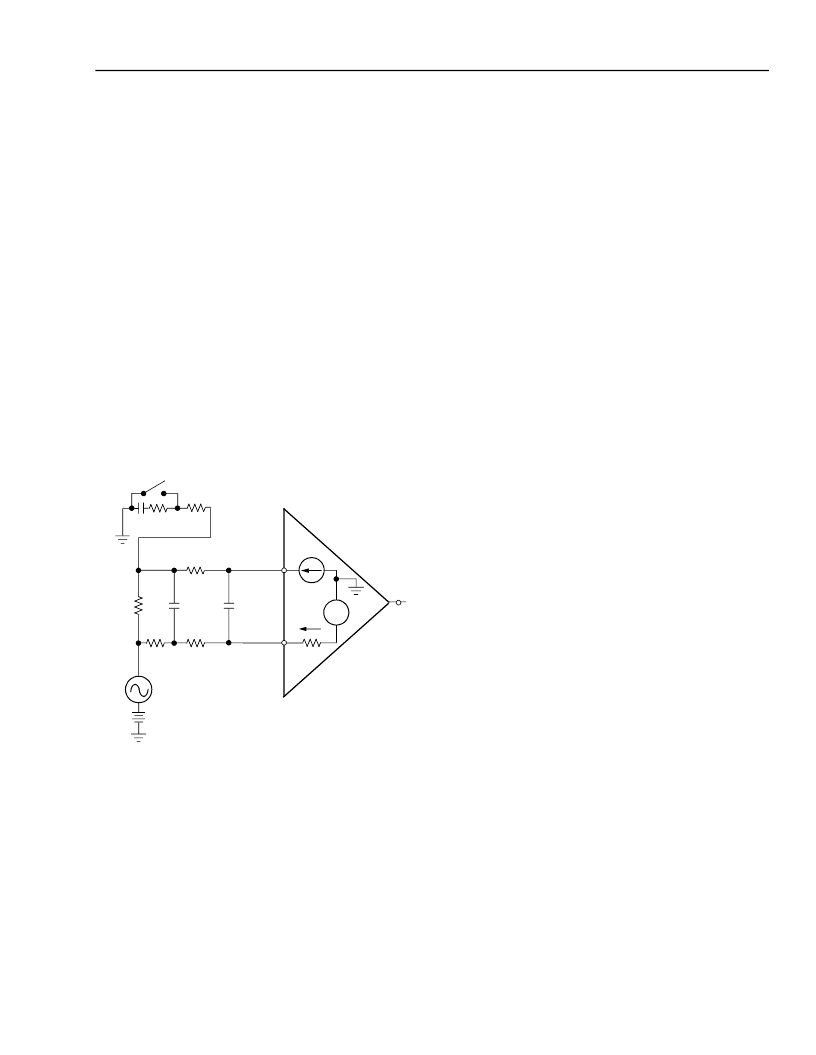
lent circuit is shown in Figure 34, along with its use
in an application using unbalanced, battery-backed
ringing.
12-3014.c (F)
Figure 34. Ring Trip Equivalent Circuit and
Equivalent Application
The comparator input voltage compliance is V
CC
to
V
BAT
, and the maximum current is 240
μ
A in either
direction. Its application is straightforward. A resistance
(R
TSN
+ R
TS2
) in series with the R
TSN
input establishes a
current that is repeated in the R
TSP
input. A slightly
lower resistance (R
TSP
) is placed in series with the R
TSP
input. When ringing is being injected, no dc current
flows through R
TS1
, so the R
TSP
input is at a lower
potential than R
TSN
. When enough dc loop current
flows, the R
TSP
input voltage increases to trip the com-
parator. In Figure 34, a low-pass filter with a double
pole at 2 Hz was implemented to prevent false ring trip.
The following example illustrates how the detection cir-
cuit in Figure 34 will trip at a 12.5 mA dc loop current
using a –48 V battery.
The current I
N
is repeated as I
P
in the positive compar-
ator input. The voltage at comparator input R
TSP
is:
V
RTSP
= V
BAT
+ I
LOOP(dc)
x R
TS1
+ I
P
x R
TSP
Using this equation and the values in the example, the
voltage at input R
TSP
is –13.2 V during ringing injection
(I
LOOP(dc)
= 0). Input R
TSP
is therefore at a level of 5 V
below R
TSN
. When enough dc loop current flows
through R
TS1
to raise its dc drop to 5 V, the comparator
will trip.
In this example:
I
LOOP(dc)
=
= 12.5 mA
Except for L8560CAU, the internal voltage for
L8560CAU is –5.7 V.
Note that during ringing in this mode of operation, both
the NLC and NRDET circuits are active. During the
actual ringing, NRDET is connected and NLC is iso-
lated from tip and ring by the ring relay; thus, NSTAT
reflects the status at NRDET. During quiet intervals of
ringing, NLC is connected and NRDET is isolated from
tip and ring by the ring relay; thus, NSTAT reflects the
status at NLC. Thus, during ring cadence, the logic
input that drives the ring relay can be used as an indi-
cation as to whether NRDET or NLC appears at output
NSTAT.
A basic loop start reference circuit, using bused
ringing with the L8560 SLIC and T7504 first-generation
codec, is shown in Figure 35. This circuit is designed
for a 600
resistive termination impedance and hybrid
balance. Transmit and receive gains are both set at
0 dB.
+
–
R
TSP
R
LOOP
15 k
8.2 V
I
P
= I
N
R
TSN
R
TS2
2 M
2 M
C
RTS1
0.022
μ
F
C
RTS2
0.27
μ
F
274 k
PHONE
HOOK SWITCH
RC PHONE
V
RING
V
BAT
NRDET
R
TS1
402
R
TSP
I
N
R
TSN
–
+
I
N
2.289 M
–8.2 V – (–48)
=
17.4 μA
=
402
---5 V
相關(guān)PDF資料 |
PDF描述 |
|---|---|
| LUCL8560AP-DT | Side Entry Connector Hood; Enclosure Material:Aluminum Alloy; For Use With:C146 Rectangular Circular Connectors; Thread Size:PG 21; Connecting Termination:Screw; No. of Contacts:24; Operating Voltage:400V; Series:C-146 RoHS Compliant: Yes |
| LUCL8560AU-D | Low-Power SLIC with Ringing |
| LUCL8560AU-DT | Low-Power SLIC with Ringing |
| LUCL8560EP-D | Low-Power SLIC with Ringing |
| LUCL8567AP-D | SLIC for Peoples Republic of China Applications |
相關(guān)代理商/技術(shù)參數(shù) |
參數(shù)描述 |
|---|---|
| LUCL8560AP-DT | 制造商:Major 功能描述: |
| LUCL8560AU | 制造商:未知廠家 制造商全稱:未知廠家 功能描述:Subscriber Line Interface Circuit |
| LUCL8560AU-D | 制造商:AGERE 制造商全稱:AGERE 功能描述:Low-Power SLIC with Ringing |
| LUCL8560AU-DT | 制造商:AGERE 制造商全稱:AGERE 功能描述:Low-Power SLIC with Ringing |
| LUCL8560CAU-D | 制造商:未知廠家 制造商全稱:未知廠家 功能描述:Subscriber Line Interface Circuit |
發(fā)布緊急采購(gòu),3分鐘左右您將得到回復(fù)。