- 您現(xiàn)在的位置:買賣IC網(wǎng) > PDF目錄367613 > LUCL9214GAJ-DT Low-Cost Ringing SLIC PDF資料下載
參數(shù)資料
| 型號(hào): | LUCL9214GAJ-DT |
| 英文描述: | Low-Cost Ringing SLIC |
| 中文描述: | 低成本振鈴用戶接口 |
| 文件頁(yè)數(shù): | 28/46頁(yè) |
| 文件大小: | 790K |
| 代理商: | LUCL9214GAJ-DT |
第1頁(yè)第2頁(yè)第3頁(yè)第4頁(yè)第5頁(yè)第6頁(yè)第7頁(yè)第8頁(yè)第9頁(yè)第10頁(yè)第11頁(yè)第12頁(yè)第13頁(yè)第14頁(yè)第15頁(yè)第16頁(yè)第17頁(yè)第18頁(yè)第19頁(yè)第20頁(yè)第21頁(yè)第22頁(yè)第23頁(yè)第24頁(yè)第25頁(yè)第26頁(yè)第27頁(yè)當(dāng)前第28頁(yè)第29頁(yè)第30頁(yè)第31頁(yè)第32頁(yè)第33頁(yè)第34頁(yè)第35頁(yè)第36頁(yè)第37頁(yè)第38頁(yè)第39頁(yè)第40頁(yè)第41頁(yè)第42頁(yè)第43頁(yè)第44頁(yè)第45頁(yè)第46頁(yè)

Preliminary Data Sheet
October 2001
Low-Cost Ringing SLIC
L9214A/G
28
Agere Systems Inc.
Supervision
(continued)
Power Ring
(continued)
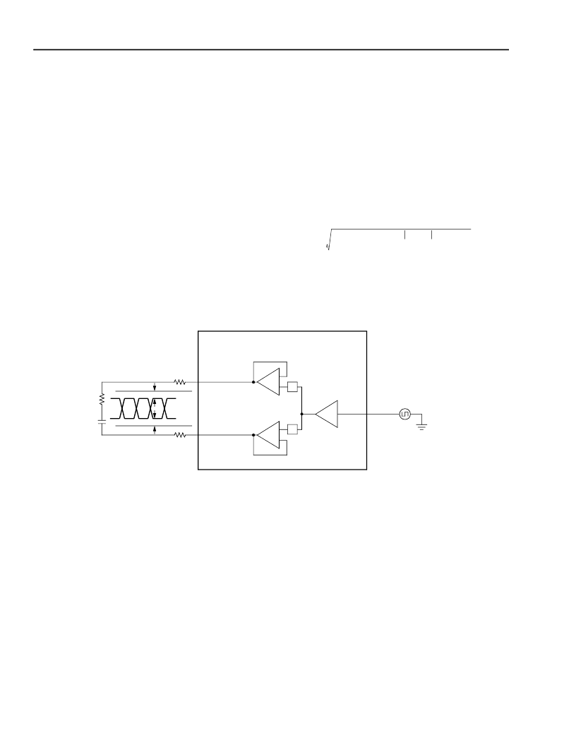
The ring signal will appear balanced on tip and ring.
That is, the ring signal is applied on both tip and ring,
with the signal on tip 180
°
out of phase from the signal
on ring. This operation is shown in Figure 12 below.
Ringing loop range is calculated as follows:
V
RINGLOAD
= {(V
BATTERY
–
4)/Crest Factor} *
{R
LOAD
/(R
LOAD
+ R
LOOP
+ 2 x R
PROTECTION
)}
As a practical example, calculate the maximum dc loop
length, assuming the following conditions:
Minimum required ring voltage = 40 Vrms
V
BATTERY
=
–
67 V
Trapezoidal ringing, crest factor = 1.2
Protection resistors = 30
each
Ring Load = 2 North American REN = 3500
+ 16
μ
F
Ringing frequency = 25 Hz
First, calculate the equivalent ringing load resistance at
25 Hz.
R
LOAD
= {(3500
)
2
+ (2 *
π
* 25 * 16E
–
6)
–
2
}
0.5
R
LOAD
= 3522
40 Vrms = {(67
–
4)/1.2)} {3522
/(R
LOOP
+ 3522
+
60
)}
R
LOOP
= 1040
Effects such as power supply tolerance and crest factor
tolerance can affect this calculation.
Crest factor is estimated by the formula:
Where:
f = ringing frequency; C
FB
= (C
FB1
+ C
FB2
)/2;
Ics = 30
μ
A with B3 = 1 and 90
μ
A with B3 = 0;
V
OHH
= 4 V
1
I
CS
×
-----------------------------------------------------------------------------------------
3
–
-------------------------------------------------------------------------------------------------------
=
12-3532.B (F)
Figure 12. Ring Operation
GND
V
BAT
RING
LOAD
1/2 R
LOOP
+ R
PROTECTION
1/2 R
LOOP
+ R
PROTECTION
PT
+1
PR
B1
SQUARE WAVE OR
PWM SIGNAL
L9214
V
TIP
V
RING
–
1
3 V
1 V
相關(guān)PDF資料 |
PDF描述 |
|---|---|
| LUCL9214GAU-D | Low-Cost Ringing SLIC |
| LUCL9214GAU-DT | Low-Cost Ringing SLIC |
| LUCL9214GRG-D | Planar E Core |
| LUCL9214GRG-DT | Low-Cost Ringing SLIC |
| LUCL9214ARG-DT | Low-Cost Ringing SLIC |
相關(guān)代理商/技術(shù)參數(shù) |
參數(shù)描述 |
|---|---|
| LUCL9214GAU-D | 制造商:AGERE 制造商全稱:AGERE 功能描述:Low-Cost Ringing SLIC |
| LUCL9214GAU-DT | 制造商:AGERE 制造商全稱:AGERE 功能描述:Low-Cost Ringing SLIC |
| LUCL9214GRG-D | 制造商:AGERE 制造商全稱:AGERE 功能描述:Low-Cost Ringing SLIC |
| LUCL9214GRG-DT | 制造商:AGERE 制造商全稱:AGERE 功能描述:Low-Cost Ringing SLIC |
| LUCL9215AAU-D | 制造商:AGERE 制造商全稱:AGERE 功能描述:Short-Loop Sine Wave Ringing SLIC |
發(fā)布緊急采購(gòu),3分鐘左右您將得到回復(fù)。