- 您現(xiàn)在的位置:買(mǎi)賣(mài)IC網(wǎng) > PDF目錄30779 > LXM1612-05-01 SPECIALTY ANALOG CIRCUIT, XMA PDF資料下載
參數(shù)資料
| 型號(hào): | LXM1612-05-01 |
| 元件分類(lèi): | 模擬信號(hào)調(diào)理 |
| 英文描述: | SPECIALTY ANALOG CIRCUIT, XMA |
| 文件頁(yè)數(shù): | 2/5頁(yè) |
| 文件大小: | 118K |
| 代理商: | LXM1612-05-01 |

5V HIGHLY-INTEGRATED, DIGITAL DIMMING CCFL INVERTER MODULE
LXM1612-05-xx
PRODUCT DA T ABOOK 1996/1997
Copyright 1999
Rev. 0.4
7/99
2
P RELIMINAR Y D AT A S HEET
P
P A
A
A TENT
TENT
P
P ENDING
ENDING
RangeMAX
TM
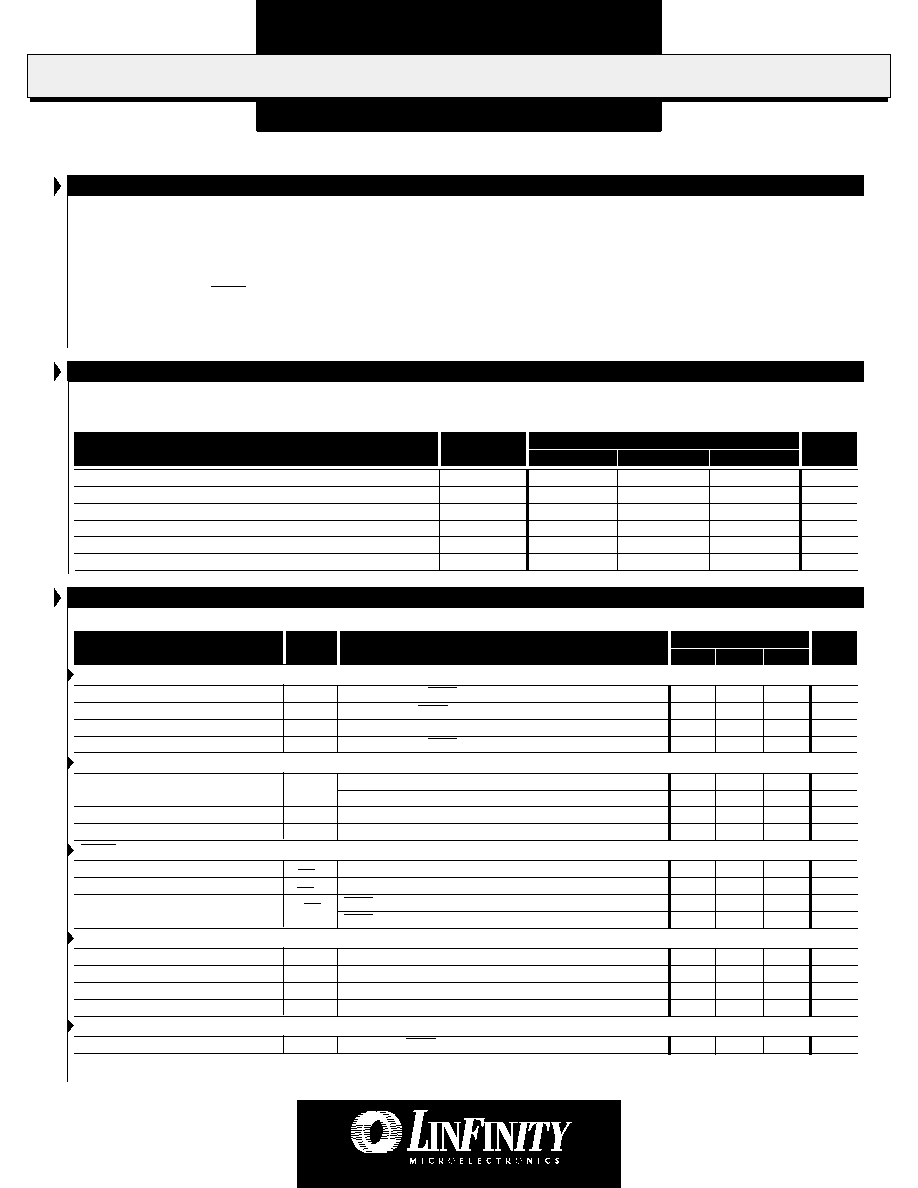
ABSOLUTE MAXIMUM RA TINGS
(Note 1)
Input Supply Voltage (V
IN1) .................................................................................................................................................... -0.3V to 6.5V
Output Voltage, no load .............................................................................................................................. Internally Limited to 1800V
RMS
Output Current .............................................................................................................................................. 8.0mA
RMS (Internally Limited)
Output Power ........................................................................................................................................................................................ 6.0W
Input Signal Voltage (BRITE Input) ............................................................................................................................... -0.3V to V
IN1+0.3V
Input Signal Voltage (SLEEP, V
SYNC Inputs) ................................................................................................................... -0.3V to VIN1+0.3V
Ambient Operating Temperature, zero airflow ........................................................................................................................ 0°C to 70°C
Storage Temperature Range ................................................................................................................................................... -40°C to 85°C
Note 1.
Exceeding these ratings could cause damage to the device. All voltages are with respect to Ground. Currents are positive into, negative out of the specified terminal.
RECOMMENDED OPERA TING CONDITIONS (R.C.)
This module has been designed to operate over a wide range of input and output conditions. However, best efficiency and performance
will be obtained if the module is operated under the condition listed in the 'R.C.' column. Min. and Max. columns indicate values beyond
which the inverter, although operational, will not function optimally.
Input Supply Voltage Range
V
IN1
Output Power
P
O
Brightness Control Input Voltage Range
V
BRT ADJ
Lamp Operating Voltage
V
LAMP
Lamp Current (Full Brightness)
I
OLAMP
Operating Ambient Temperature Range
T
A
Parameter
Symbol
Units
Recommended Operating Conditions
Min.
R.C.
Max.
4.5
5
5.5
V
3.5
4.0
W
0.0
2.5
V
IN
V
300
600
650
V
RMS
5.8
mA
RMS
070
°C
ELECTRICAL CHARACTERISTICS
Unless otherwise specified, these specifications apply over the recommended operating conditions and 25°C ambient temperature for the LXM1612-05-xx.
Full Bright Lamp Current
I
L (MAX)
V
BRT ADJ = 2.5VDC, SLEEP = HIGH, Burst Duty=100%, VIN1 =5VDC
Min. Average Lamp Current (Note 2)
I
L (MIN)
V
BRT ADJ = 0VDC, SLEEP = HIGH, Burst Duty = 2.0%, VIN1 =5VDC
Lamp Start Voltage
V
LS
0°C < T
A < 40°C, VIN1 ≥ 5.0VDC
Operating Frequency
f
O
V
BRT ADJ = 2.5VDC, SLEEP = HIGH, VIN1 = 5VDC
Output Pin Characteristics
Parameter
Symbol
Test Conditions
Units
LXM1612-05-xx
Min.
Typ.
Max.
5.8
mA
RMS
0.12
mA
RMS
1500
1650
1800
V
RMS
63
68
73
KHz
BRITE Input
Input Current
I
BRT
V
BRT ADJ = 0VDC
V
BRT ADJ = 2.5VDC
Input Voltage for Max. Lamp Current
V
BRT ADJ
I
O (LAMP) = 100% Duty Cycle
Input Voltage for Min. Lamp Current
V
BRT ADJ
I
O (LAMP) = Minimum Duty Cycle
-685
-728
-775
A
DC
-260
-282
-305
A
DC
2.30
2.35
2.40
V
DC
0.0
V
DC
1.9
2.1
V
IN1
V
DC
-5.0
1.9
2.0
V
DC
390
410
435
A
DC
0.0
A
DC
Power Characteristics
Sleep Current
I
IN (MIN)
V
IN1 = 5VDC , SLEEP = 0.0V
0.0
0.5
10
A
DC
RUN Mode
V
SLEEP (HI)
V
IN1 = 4.5V
SLEEP Mode
V
SLEEP (LO)
V
IN1 = 5.5V
Input Current
I
SLEEP
SLEEP = 5.0V
SLEEP = 0V
SLEEP Input
Note 2. Minimum lamp current required to maintain even light output may vary with display panel.
Average RMS current = (burst duty cycle) x (burst amplitude of 5.8mA
RMS)
V
SYNC Characteristics
Logic High Level
V
SYNCH (HI)
V
IN1 = 4.5V
Logic Low Level
V
SYNCH (LO)
V
IN1 = 5.5V
Input Impedance
Z
IN
Input Frequency
f
SYNC
1.50
2.5
5.0
V
DC
-3.0
0.0
1.2
V
DC
25
27
29
k
20
200
Hz
相關(guān)PDF資料 |
PDF描述 |
|---|---|
| LXM1617-12-41 | SPECIALTY ANALOG CIRCUIT, XMA |
| LXM1617-12-42 | SPECIALTY ANALOG CIRCUIT, XMA |
| LXM1617-12-43 | SPECIALTY ANALOG CIRCUIT, XMA |
| LXM1641-03 | SPECIALTY ANALOG CIRCUIT, XMA |
| LY3100ALH | SPECIALTY ANALOG CIRCUIT, PBGA10 |
相關(guān)代理商/技術(shù)參數(shù) |
參數(shù)描述 |
|---|---|
| LXM1612-05-01B | 制造商:Microsemi Corporation 功能描述:LXM1612-05-01B - Tape and Reel |
| LXM1612-05-02 | 功能描述:MOD INVERTER CCFL DIGITAL SGL 5V RoHS:否 類(lèi)別:光電元件 >> 反相器 系列:LXM1612-05-xx 標(biāo)準(zhǔn)包裝:100 系列:- 輸入電壓:6.0V 輸出:900V 類(lèi)型:用于 CCFL 和 UV 燈的逆變器 尺寸/尺寸:2.34" L x 0.35" W x 0.35" H(59.5mm x 9mm x 8.9mm) 安裝類(lèi)型:底座安裝 |
| LXM1612-05-03 | 功能描述:MOD INVERTER CCFL DIGITAL SGL 5V RoHS:否 類(lèi)別:光電元件 >> 反相器 系列:LXM1612-05-xx 標(biāo)準(zhǔn)包裝:100 系列:- 輸入電壓:6.0V 輸出:900V 類(lèi)型:用于 CCFL 和 UV 燈的逆變器 尺寸/尺寸:2.34" L x 0.35" W x 0.35" H(59.5mm x 9mm x 8.9mm) 安裝類(lèi)型:底座安裝 |
| LXM1612-05-XX | 制造商:MICROSEMI 制造商全稱(chēng):Microsemi Corporation 功能描述:5V Highly-Integrated, Digital Dimming CCFL Inverter Module |
| LXM1612-12-01 | 功能描述:MOD INVERTER CCFL DGTL SGL 12V RoHS:否 類(lèi)別:光電元件 >> 反相器 系列:LXM1612-12-xx 標(biāo)準(zhǔn)包裝:100 系列:- 輸入電壓:6.0V 輸出:900V 類(lèi)型:用于 CCFL 和 UV 燈的逆變器 尺寸/尺寸:2.34" L x 0.35" W x 0.35" H(59.5mm x 9mm x 8.9mm) 安裝類(lèi)型:底座安裝 |
發(fā)布緊急采購(gòu),3分鐘左右您將得到回復(fù)。