- 您現(xiàn)在的位置:買賣IC網(wǎng) > PDF目錄376117 > LXMG1618-05-2X (Microsemi Corporation) 5V 2.2W CCFL Programmable Inverter Module PDF資料下載
參數(shù)資料
| 型號: | LXMG1618-05-2X |
| 廠商: | Microsemi Corporation |
| 英文描述: | 5V 2.2W CCFL Programmable Inverter Module |
| 中文描述: | 5V的2.2W的冷陰極可編程變頻器模塊 |
| 文件頁數(shù): | 2/6頁 |
| 文件大小: | 176K |
| 代理商: | LXMG1618-05-2X |

P
RODUCTION
D
ATASHEET
Microsemi
Integrated Products
11861 Western Avenue, Garden Grove, CA. 92841, 714-898-8121, Fax: 714-893-2570
Page 2
Copyright
2002
Rev. 1.0a,2006-11-13
W
M
.
C
PanelMatch
LXMG1618-05-2x
5V 2.2W CCFL Programmable Inverter Module
TM
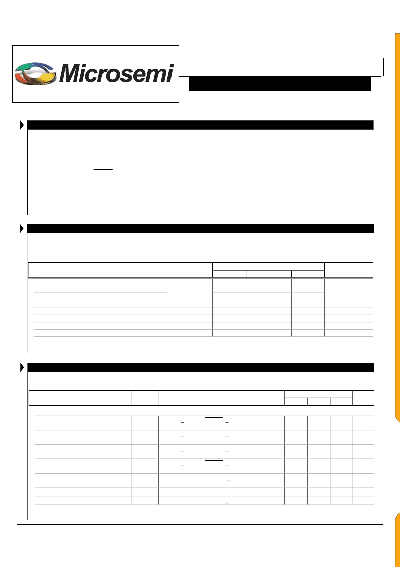
A B S O L U T E M A X I M U M R A T I N G S
( N O T E 1 )
Input Signal Voltage (V
IN1
)....................................................................................................................................-0.3V to 6.5V
Input Power...................................................................................................................................................................... 3.0W
Output Voltage, no load ............................................................................................................Internally Limited to 1300V
RMS
Output Current ............................................................................................................................6.5mA
RMS
(Internally Limited)
Output Power................................................................................................................................................................... 2.3W
Input Signal Voltage (
SLEEP
Input)....................................................................................................................-0.3V to 5.5V
Input Signal Voltage (BRITE)...............................................................................................................................-0.3V to 5.5V
Ambient Operating Temperature, zero airflow.....................................................................................................-20°C to 70°C
Storage Temperature Range...............................................................................................................................-40°C to 85°C
Note 1: Exceeding these ratings could cause damage to the device. All voltages are with respect to Ground. Currents are positive into, negative out of specified
terminal.
R E C O M M E N D E D O P E R A T I N G C O N D I T I O N S ( R . C . )
This module has been designed to operate over a wide range of input and output conditions. However, best efficiency and performance
will be obtained if the module is operated under the condition listed in the ‘R.C.’ column. Min. and Max. columns indicate values beyond
which the inverter, although operational, will not function optimally.
Recommended Operating Conditions
Min
R.C.
Parameter
Symbol
Max
Units
Input Supply Voltage Range (Fully Regulated
Lamp Current)
Input Supply Voltage Range (Functional)
Output Power
Linear BRITE Control Input Voltage Range1
Lamp Operating Voltage
Lamp Current (Full Brightness)
Operating Ambient Temperature Range
1The minimum V
BRT ADJ
voltage depends on the panel characteristics, depending on the panel it can vary from 0.65V to 0.9V
* Total output power must not exceed 4W. Higher voltage lamps may require maximum output current to be set lower than 5mA
RMS
4.75
5
5.25
V
IN1
4.5
5
5.5
2.2
2.0
435*
5.0
70
V
P
O
W
V
V
RMS
mA
RMS
°C
V
BRT_ADJ
V
LAMP
I
OLAMP
T
A
0.65 to 0.9
325
3.5
-20
380
E L E C T R I C A L C H A R A C T E R I S T I C S
Unless otherwise specified, the following specifications apply over the recommended operating condition and ambient temperature of
25
°
C except where otherwise noted.
LXMG1618-05-2x
Min
Typ
`
OUTPUT PIN CHARACTERISTICS
Parameter
Symbol
Test Conditions
Max
Units
Full Bright Lamp Current
I
L(MAX)
V
BRT_ADJ
> 2.0V
DC
,
SLEEP
> 2.0V, V
IN1
= 5V
DC
I
SET1
= Ground, I
SET2
= Ground
V
BRT_ADJ
> 2.0V
DC
,
SLEEP
> 2.0V, V
IN1
= 5V
DC
I
SET1
= Ground, I
SET2
= Open
V
BRT_ADJ
> 2.0V
DC
,
SLEEP
> 2.0V, V
IN1
= 5V
DC
I
SET1
= Open, I
SET2
= Ground
V
BRT_ADJ
> 2.0V
DC
,
SLEEP
> 2.0V, V
IN1
= 5V
DC
I
SET1
= Open, I
SET2
= Open
V
BRT_ADJ
=0.65V
DC
,
SLEEP
> 2.0V, V
IN1
= 5V
DC
I
SET1
= I
SET2
= Ground
-20°C < T
A
< 70°C, V
IN1
> 4.5V
DC
V
BRT_ADJ
= 2.5V
DC
,
SLEEP
> 2.0V, V
IN1
= 5V
3.0
3.5
4.0
mA
RMS
Full Bright Lamp Current
I
L(MAX)
3.5
4.0
4.5
mA
RMS
Full Bright Lamp Current
I
L(MAX)
4.0
4.5
5.0
mA
RMS
Full Bright Lamp Current
I
L(MAX)
4.5
5
5.5
mA
RMS
Min. Average Lamp Current
Lamp Start Voltage
Operating Frequency
I
L(MIN)
1.5*
mA
RMS
V
LS
f
O
1000
85
1100
90
V
RMS
kHz
94
* The inverter is capable of a lower output current than may be recommended by the panel manufacturer. It is the user’s responsibility to set the minimum
brightness (BRITE) input at or above the panel specification for minimum current.
E
L
E
C
T
R
I
C
A
L
S
相關(guān)PDF資料 |
PDF描述 |
|---|---|
| LXMG1618-05-41 | 5V 4W CCFL Programmable Inverter Module |
| LXMG1618-05-42 | 5V 4W CCFL Programmable Inverter Module |
| LXMG1618-05-4X | 5V 4W CCFL Programmable Inverter Module |
| LXMG1618-05-61 | 5V 6W CCFL Programmable Inverter Module |
| LXMG1618-05-62 | 5V 6W CCFL Programmable Inverter Module |
相關(guān)代理商/技術(shù)參數(shù) |
參數(shù)描述 |
|---|---|
| LXMG1618-05-41 | 制造商:MICROSEMI 制造商全稱:Microsemi Corporation 功能描述:5V 4W CCFL Programmable Inverter Module |
| LXMG1618-05-42 | 制造商:Microsemi Corporation 功能描述:CCFL Inverter Single Lamp 3.5W 80KHz 10-Pin 制造商:Microsemi Corporation 功能描述:CCFL INVERTER SGL LAMP 3.5W 80KHZ - Bulk |
| LXMG1618-05-43 | 功能描述:MOD INVERTER CCFL 4W 5V PROG RoHS:是 類別:光電元件 >> 反相器 系列:LXMG1618-05-4x 標(biāo)準(zhǔn)包裝:100 系列:- 輸入電壓:6.0V 輸出:900V 類型:用于 CCFL 和 UV 燈的逆變器 尺寸/尺寸:2.34" L x 0.35" W x 0.35" H(59.5mm x 9mm x 8.9mm) 安裝類型:底座安裝 |
| LXMG1618-05-4X | 制造商:MICROSEMI 制造商全稱:Microsemi Corporation 功能描述:5V 4W CCFL Programmable Inverter Module |
| LXMG1618-05-61 | 功能描述:MOD INVERTER CCFL 6W 5V PROG RoHS:是 類別:光電元件 >> 反相器 系列:LXMG1618-05-6x 標(biāo)準(zhǔn)包裝:100 系列:- 輸入電壓:6.0V 輸出:900V 類型:用于 CCFL 和 UV 燈的逆變器 尺寸/尺寸:2.34" L x 0.35" W x 0.35" H(59.5mm x 9mm x 8.9mm) 安裝類型:底座安裝 |
發(fā)布緊急采購,3分鐘左右您將得到回復(fù)。