- 您現(xiàn)在的位置:買賣IC網(wǎng) > PDF目錄376120 > M18SP6D (Electronic Theatre Controls, Inc.) Stainless Steel 18 mm Barrel-style DC Photoelectric Sensors PDF資料下載
參數(shù)資料
| 型號: | M18SP6D |
| 廠商: | Electronic Theatre Controls, Inc. |
| 英文描述: | Stainless Steel 18 mm Barrel-style DC Photoelectric Sensors |
| 中文描述: | 18毫米不銹鋼桶式直流光電傳感器 |
| 文件頁數(shù): | 3/8頁 |
| 文件大?。?/td> | 179K |
| 代理商: | M18SP6D |

EZ-BEAM M18 Series Sensors
page
3
Banner Engineering Corp.
Minneapolis, U.S.A.
Website: http://www.baneng.com Tel: 888.373.6767
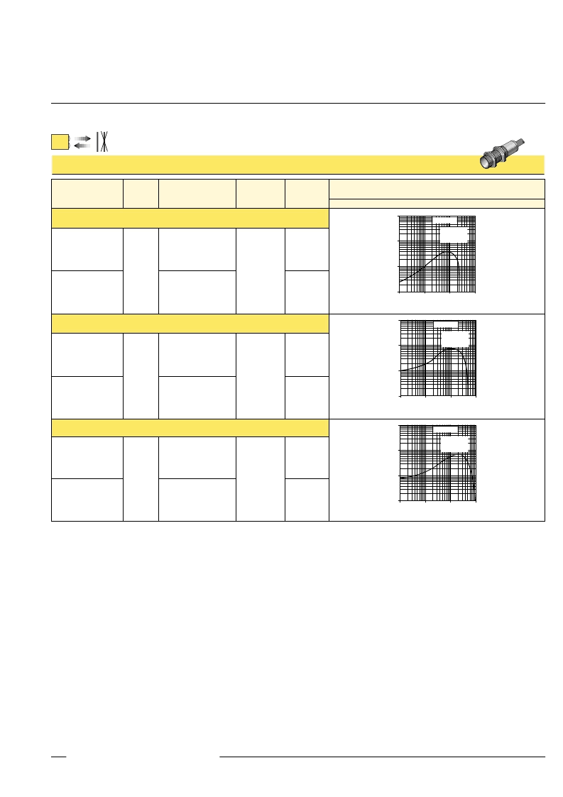
M18 Series Fixed-Field Mode
M18SP6FF100
M18SP6FF100Q
2 m (6.5')
4-Pin Euro-style QD
Models
Cutoff
Point
Cable
Supply
Voltage
Output
Type
Excess Gain
Performance based on 90% reflectance white test card
M18SN6FF100
M18SN6FF100Q
100 mm
(4")
2 m (6.5')
4-Pin Euro-style QD
10-30V dc
NPN
M18SP6FF25
M18SP6FF25Q
With 100 mm Far Limit Cutoff
PNP
2 m (6.5')
4-Pin Euro-style QD
1
.1 mm
.004 in
10
100
1 mm
.04 in
DISTANCE
10 mm
.4 in
100 mm
4 in
E
X
C
E
S
S
G
A
I
N
1000
M18 Series
Fixed-field mode
with 100 mm far
limit cutoff
M18SN6FF25
M18SN6FF25Q
25 mm
(1")
2 m (6.5')
4-Pin Euro-style QD
10-30V dc
NPN
With 25 mm Far Limit Cutoff
PNP
1
.1 mm
.004 in
10
100
1 mm
.04 in
DISTANCE
10 mm
.4 in
100 mm
4 in
E
X
C
E
S
S
G
A
I
N
1000
M18 Series
Fixed-field mode
with 25 mm far
limit cutoff
M18SP6FF50
M18SP6FF50Q
2 m (6.5')
4-Pin Euro-style QD
M18SN6FF50
M18SN6FF50Q
50 mm
(2")
2 m (6.5')
4-Pin Euro-style QD
10-30V dc
NPN
With 50 mm Far Limit Cutoff
PNP
1
.1 mm
.004 in
10
100
1 mm
.04 in
DISTANCE
10 mm
.4 in
100 mm
4 in
E
X
C
E
S
S
G
A
I
N
1000
M18 Series
Fixed-field mode
with 50 mm far
limit cutoff
* 9 m (30') cables are available by adding suffix
“
W/30
”
to the model number of any cabled sensor (e.g.,
M18SN6FF25 W/30
).
A model with a QD connector requires an optional mating cable. See page 6 for more information.
Infrared, 880 nm
The excess gain curves above show
excess gain vs. sensing distance for M18
Series fixed-field sensors with 25-, 50- and
100-millimeter cutoffs. Maximum excess
gain for the 25-mm models occurs at a
lens-to-object distance of about 7 mm; for
the 50-mm models, at about 10 mm; and
for the 100-mm models, at about 20 mm.
Sensing at or near these distances will
make maximum use of each sensor’s
available sensing power.
Backgrounds and background objects
must
always
be placed beyond the cutoff
distance.
These excess gain curves were generated
using a white test card of 90% reflectance.
Objects with reflectivity of less than 90%
reflect less light back to the sensor, and
thus require proportionately more excess
gain in order to be sensed with the same
reliability as more reflective objects. When
sensing an object of very low reflectivity, it
may be especially important to sense it at or
near the distance of maximum excess gain.
The effects of object reflectivity on cutoff
distance, though small, may be important
for some applications. Sensing of objects
of less than 90% reflectivity causes the
cutoff distances to be “pulled” slightly
closer to the sensor. For example, an
excess gain of 1 for an object that reflects
1/10 as much light as the 90% white card
is represented by the heavy horizontal
graph line at excess gain = 10. An object
of this reflectivity results in far limit cutoffs
of approximately 20, 40 and 70 mm (for
25-, 50- and 100-mm cutoff models,
respectively).
Objects with reflectivity greater than 90%
return more light to the sensor. For this
reason, highly reflective backgrounds or
background objects such as mirrors, pol-
ished metal, and other sources of specular
reflections require special consideration. If
it is necessary to use a highly reflective
background, it should be placed as far
beyond the cutoff distance as possible and
angled to direct reflected light away from
the sensor (see page 4).
相關(guān)PDF資料 |
PDF描述 |
|---|---|
| M18SP6DL | Stainless Steel 18 mm Barrel-style DC Photoelectric Sensors |
| M18SP6DLQ | Stainless Steel 18 mm Barrel-style DC Photoelectric Sensors |
| M18SP6DQ | Stainless Steel 18 mm Barrel-style DC Photoelectric Sensors |
| M18SP6FF100 | Stainless Steel 18 mm Barrel-style DC Photoelectric Sensors |
| M18SP6FF100Q | Stainless Steel 18 mm Barrel-style DC Photoelectric Sensors |
相關(guān)代理商/技術(shù)參數(shù) |
參數(shù)描述 |
|---|---|
| M18SP6DL | 制造商:未知廠家 制造商全稱:未知廠家 功能描述:Stainless Steel 18 mm Barrel-style DC Photoelectric Sensors |
| M18SP6DLQ | 制造商:Banner Engineering 功能描述:Sensor, Photoelectric, Diffuse, 300mm Range, 10-30VDC, PNP, QD Connector |
| M18SP6DLQ-72226 | 制造商:Banner Engineering 功能描述:M18SP6DLQ-72226 LABLED MOELLER NO BANNER MARKINGS BULK PACK |
| M18SP6DQ | 制造商:Banner Engineering 功能描述:Sensor, Photoelectric, Diffuse, 100mm Range, 10-30VDC, PNP, QD Connector |
| M18SP6FF100 | 制造商:未知廠家 制造商全稱:未知廠家 功能描述:Stainless Steel 18 mm Barrel-style DC Photoelectric Sensors |
發(fā)布緊急采購,3分鐘左右您將得到回復(fù)。