- 您現(xiàn)在的位置:買賣IC網(wǎng) > PDF目錄69009 > M30625MGN-XXXGP 16-BIT, MROM, 16 MHz, MICROCONTROLLER, PQFP80 PDF資料下載
參數(shù)資料
| 型號(hào): | M30625MGN-XXXGP |
| 元件分類: | 微控制器/微處理器 |
| 英文描述: | 16-BIT, MROM, 16 MHz, MICROCONTROLLER, PQFP80 |
| 封裝: | 14 X 14 MM, 0.65 MM PITCH, PLASTIC, QFP-80 |
| 文件頁(yè)數(shù): | 28/67頁(yè) |
| 文件大?。?/td> | 2968K |
| 代理商: | M30625MGN-XXXGP |
第1頁(yè)第2頁(yè)第3頁(yè)第4頁(yè)第5頁(yè)第6頁(yè)第7頁(yè)第8頁(yè)第9頁(yè)第10頁(yè)第11頁(yè)第12頁(yè)第13頁(yè)第14頁(yè)第15頁(yè)第16頁(yè)第17頁(yè)第18頁(yè)第19頁(yè)第20頁(yè)第21頁(yè)第22頁(yè)第23頁(yè)第24頁(yè)第25頁(yè)第26頁(yè)第27頁(yè)當(dāng)前第28頁(yè)第29頁(yè)第30頁(yè)第31頁(yè)第32頁(yè)第33頁(yè)第34頁(yè)第35頁(yè)第36頁(yè)第37頁(yè)第38頁(yè)第39頁(yè)第40頁(yè)第41頁(yè)第42頁(yè)第43頁(yè)第44頁(yè)第45頁(yè)第46頁(yè)第47頁(yè)第48頁(yè)第49頁(yè)第50頁(yè)第51頁(yè)第52頁(yè)第53頁(yè)第54頁(yè)第55頁(yè)第56頁(yè)第57頁(yè)第58頁(yè)第59頁(yè)第60頁(yè)第61頁(yè)第62頁(yè)第63頁(yè)第64頁(yè)第65頁(yè)第66頁(yè)第67頁(yè)
35
MITSUBISHI MICROCOMPUTERS
4551 Group
SINGLE-CHIP 4-BIT CMOS MICROCOMPUTER for
INFRARED REMOTE CONTROL TRANSMITTER
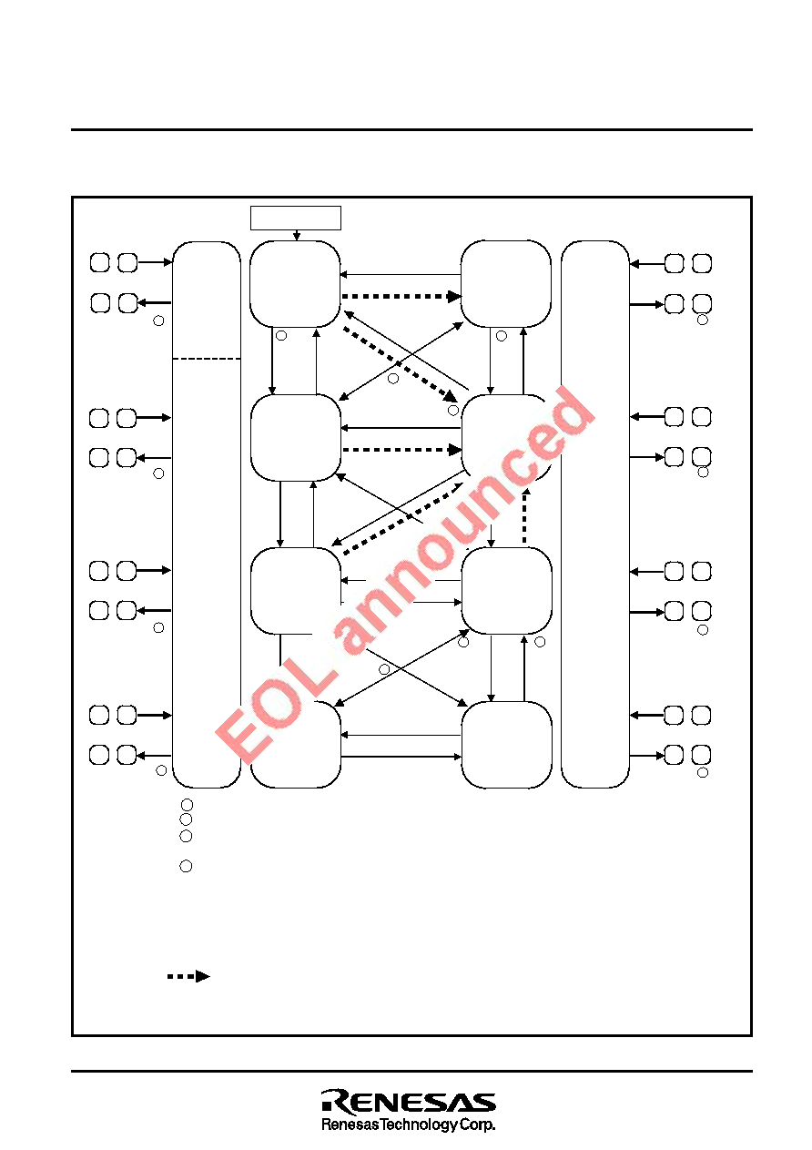
(8) State transition
State transition is described using Figure 36.
Fig. 36 State transition
MR
0
←
0
B
MR
0
←
1
C
MR
1
←
1
MR
1
←
0
D
K
A
MR
2
←
1
MR
0
←
0
F
MR
0
←
1
G
MR
1
←
1
MR
1
←
0
H
MR
2
←
0
E
MR
2
←
1
MR3
← 1
MR3
← 0
MR3
← 1
MR3
← 0
MR3
← 1
MR3
← 0
MR3
← 1
MR3
← 0
(Note 2)
(Stabilizing
time
c
)
(Stabilizing
time
c
)
J
f(XIN):Stop
f(XCIN) :
Oscillation
I
(Stabilizing
time
c )
(Stabilizing
time
c )
(Stabilizing
time
d ) (Stabilizing
time
d )
B
, F
C
, G
D
, H
B
, F
C
, G
D
, H
A
, E
A
, E
B
, F
C
, G
D
, H
B
, F
C
, G
D
, H
A
, E
(Note 2)
Reset
POF execution
Return input 1
(Stabilizing time a )
POF execution
Return input 1, 2
(Stabilizing time a )
POF execution
Return input 1, 2
(Stabilizing time c )
(Note 1)
Clock
operating
mode
POF execution
Return input 1, 2
(Stabilizing time c )
(Note 1)
f(XIN):Stop
f(XCIN):Stop
Clock
operating
mode
f(XIN):Oscillation
f(XCIN):Stop
System clock;
f(XIN)/4
MR=(10002)
MR
2
←
0
f(XIN):Oscillation
f(XCIN):Oscillation
f(XIN):Oscillation
f(XCIN):Oscillation
f(XIN):Stop
f(XCIN):Oscillation
System clock;
f(XIN)/4
MR=(11002)
System clock;
f(XCIN)/4
MR=(11012)
System clock;
f(XCIN)/4
MR=(11112)
f(XIN):Oscillation
f(XCIN):Stop
System clock;
f(XIN)
MR=(00002)
f(XIN):Oscillation
f(XCIN):Oscillation
System clock;
f(XIN)
MR=(01002)
f(XIN):Oscillation
f(XCIN):Oscillation
System clock;
f(XCIN)
MR=(01012)
f(XIN):Stop
f(XCIN):Oscillation
System clock;
f(XCIN)
MR=(01112)
(Stabilizing
time
d
)
(Stabilizing
time
d
)
(Note 2)
POF2 execution
Return input 1
(Stabilizing time a )
POF2 execution
Return input 1
(Stabilizing time a )
POF2 execution
Return input 1
(Stabilizing time b )
POF2 execution
Return input 1
(Stabilizing time b )
f(XIN):Stop
f(XCIN):Stop
RAM
back-up
mode
Stabilizing time a : An interval required to stabilize the f(XIN) oscillation is automatically generated by hardware.
Stabilizing time b : An interval required to stabilize the f(XCIN) oscillation is automatically generated by hardware.
Stabilizing time c : Generate an interval required to stabilize the f(XIN) oscillation in state C or G by software at the
transition D
→C, D→G, H→C, H→G, J→C, or J→G.
Stabilizing time d : Generate an interval required to stabilize the f(XCIN) oscillation in state B, F by software at the
transition A
→B, E→F, A→F, or E→B.
Return input 1: External wakeup signal (P00–P03, P10–P13)
Return input 2: Timer 2 interrupt request flag
Notes 1. MR3=“1”
→The microcomputer starts its operation after counting f(XCIN) clock signal 59 to 70 times.
MR3=“0”
→The microcomputer starts its operation after counting f(XCIN) clock signal 32 to 43 times.
2. When the following 2 conditions are satisfied, the transition A
→E, B→F, A→F, C→F, G→F represented
by “
” can be executed.
(1) VDD = 2.2 V to 5.5 V (One Time PROM version: VDD = 2.5 V to 5.5 V), f(XIN)
≤ 1.0 MHz
(2) VDD = 4.5 V to 5.5 V, f(XIN)
≤ 2.0 MHz
A
, E
MR
2 ←
0
MR
3 ←
0
MR
2 ←
1
MR
3 ←
1
(Note 2)
MR
2
←
1
MR
2
←
0
MR
3
←
0
MR
3
←
1
MR
3
←
1
MR
0
←
0
MR
3
←
0
MR
0
←
1
MR
0 ←
1
MR
0 ←
0
MR
3 ←
1
MR
3 ←
0
MR
3
←
1
MR
1
←
0
MR
3
←
0
MR
1
←
1
MR
1 ←
0
MR
3 ←
0
MR
1 ←
1
MR
3 ←
1
相關(guān)PDF資料 |
PDF描述 |
|---|---|
| M30625FGNGP | 16-BIT, FLASH, 16 MHz, MICROCONTROLLER, PQFP80 |
| M30621FCNGP | 16-BIT, FLASH, 16 MHz, MICROCONTROLLER, PQFP80 |
| M3062GF8NFP | 16-BIT, FLASH, 10 MHz, MICROCONTROLLER, PQFP100 |
| M3062GF8NGP | 16-BIT, FLASH, 10 MHz, MICROCONTROLLER, PQFP100 |
| M3062GF8NGP | 16-BIT, FLASH, 10 MHz, MICROCONTROLLER, PQFP100 |
相關(guān)代理商/技術(shù)參數(shù) |
參數(shù)描述 |
|---|---|
| M30625MGP | 制造商:RENESAS 制造商全稱:Renesas Technology Corp 功能描述:SINGLE-CHIP 16-BIT CMOS MICROCOMPUTER |
| M30625MGP-XXXGP | 制造商:RENESAS 制造商全稱:Renesas Technology Corp 功能描述:SINGLE-CHIP 16-BIT CMOS MICROCOMPUTER |
| M30625MG-XXXGP | 制造商:RENESAS 制造商全稱:Renesas Technology Corp 功能描述:SINGLE-CHIP 16-BIT CMOS MICROCOMPUTER |
| M30625MHP-XXXGP | 制造商:RENESAS 制造商全稱:Renesas Technology Corp 功能描述:SINGLE-CHIP 16-BIT CMOS MICROCOMPUTER |
| M30625MWP | 制造商:RENESAS 制造商全稱:Renesas Technology Corp 功能描述:SINGLE-CHIP 16-BIT CMOS MICROCOMPUTER |
發(fā)布緊急采購(gòu),3分鐘左右您將得到回復(fù)。