- 您現(xiàn)在的位置:買賣IC網(wǎng) > PDF目錄370898 > M38190EF-XXXFP (Mitsubishi Electric Corporation) HEATSINK,VERT,TO-220,CLIP PDF資料下載
參數(shù)資料
| 型號(hào): | M38190EF-XXXFP |
| 廠商: | Mitsubishi Electric Corporation |
| 英文描述: | HEATSINK,VERT,TO-220,CLIP |
| 中文描述: | 單芯片8位CMOS微機(jī) |
| 文件頁數(shù): | 28/60頁 |
| 文件大小: | 664K |
| 代理商: | M38190EF-XXXFP |
第1頁第2頁第3頁第4頁第5頁第6頁第7頁第8頁第9頁第10頁第11頁第12頁第13頁第14頁第15頁第16頁第17頁第18頁第19頁第20頁第21頁第22頁第23頁第24頁第25頁第26頁第27頁當(dāng)前第28頁第29頁第30頁第31頁第32頁第33頁第34頁第35頁第36頁第37頁第38頁第39頁第40頁第41頁第42頁第43頁第44頁第45頁第46頁第47頁第48頁第49頁第50頁第51頁第52頁第53頁第54頁第55頁第56頁第57頁第58頁第59頁第60頁

28
3819 Group
SINGLE-CHIP 8-BIT CMOS MICROCOMPUTER
MITSUBISHI MICROCOMPUTERS
(2.3) When Selecting the Internal Clock
When selecting the internal clock, the P6
7
/S
RDY1
/CS/S
CLK12
pin
can be used as the S
RDY1
pin by setting SC1
4
to “1”.
When selecting the internal clock, the P6
7
pin can be used as the
synchronous clock output pin S
CLK12
by setting SIOAC
3
to “1”. In
this case, the S
CLK11
pin goes to high impedance state.
Select the function of the P6
7
/S
RDY1
/CS/S
CLK12
and P6
6
/S
CLK11
with the following registers (refer to Table GA-1):
G
the bit 3 (SC1
3
), the bit 4(SC1
4
), and the bit 6(SC1
6
) of the se-
rial I/O1 control register
G
the bit 3 (SIOAC
3
) of the serial I/O automatic transfer control
register
When using both the S
CLK11
and S
CKL12
by switching, switch the
P6
7
/S
RDY1
/CS/S
CLK12
to the P6
7
(SC1
4
=0) and set the P6
7
direc-
tion register to input mode. Note that switch SIOAC
3
during “H” of
transfer clock at the completion of automatic transfer.
Table GA-1. S
CLK11
and S
CLK12
selection
SC1
6
1
SC1
4
0
SC3
3
1
SIOAC
3
0
1
P6
6
/S
CLK11
S
CLK11
High
impedance
P6
7
/S
CLK12
P6
7
S
CLK12
Note :
SC1
3
: Serial I/O1 port selection bit
SC1
4
: S
RDY1
output selection bit
SC1
6
: Synchronous clock selection bit
SIOAC
3
: Synchronous clock output pin selection bit
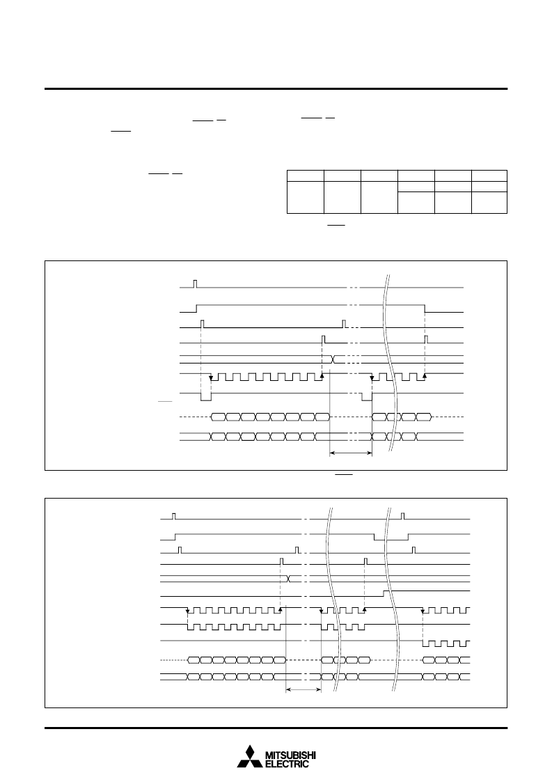
Fig. GA-8 Timing diagram during serial I/O automatic transfer (internal clock selected, S
RDY
used)
Fig. GA-9 Timing during serial I/O automatic transfer (internal clock selected, S
CLK11
and S
CLK12
used)
DI
6
DI
0
DO
0
DO
7
Bit 1 write signal of serial I/O
automatic transfer control
register
Serial I/O output
S
out
Serial I/O input
S
IN
DI
0
Transfer interval
Bit 1 of serial I/O automatic
transfer control register
Write signal from RAM to
serial I/O1 register
Write signal from serial I/O1
register to RAM
Transfer clock
Data pointer
(internal or S
CLK
output)
Receive
enabled signal
S
RDY
n-1
0
n
DO
1
DO
2
DO
3
DO
4
DO
5
DO
6
DO
7
DO
6
DI
1
DI
2
DI
3
DI
4
DI
5
DI
6
DI
7
DI
7
DO
0
DI
7
Bit 1 write signal of serial I/O
automatic transfer control
register
Bit 1 of serial I/O automatic
transfer control register
Write signal from RAM to
serial I/O1 register
Write signal from serial I/O1
register to RAM
Serial I/O output
S
out
Serial I/O input
S
IN
Transfer interval
Data pointer
m-1
0
m
DO
0
Bit 3 of serial I/O automatic
transfer control register
Transfer clock
(internal)
S
CLK11
output
S
CLK12
output
n
DO
1
DO
2
DO
3
DO
4
DO
5
DO
6
DO
7
DO
0
DO
6
DO
7
DO
0
DO
1
DO
2
DO
3
DI
0
DI
1
DI
2
DI
3
DI
4
DI
5
DI
6
DI
7
DI
0
DI
0
DI
1
DI
2
DI
3
DI
6
相關(guān)PDF資料 |
PDF描述 |
|---|---|
| M38190EF-XXXFS | IC EEPROM, SERIAL, I2C, 1K, WRITE PROT., 2.7V-5.5V SOIC8 |
| M38190M2-XXXFP | SINGLE-CHIP 8-BIT CMOS MICROCOMPUTER |
| M38190M7-XXXFP | SINGLE-CHIP 8-BIT CMOS MICROCOMPUTER |
| M38190M8-XXXFP | SINGLE-CHIP 8-BIT CMOS MICROCOMPUTER |
| M38190M9-XXXFP | Thick Film Resistor Array; Series:CRB; Resistance:68ohm; Resistance Tolerance: 5%; Power Rating:0.063W; Operating Temperature Range:-55 C to ? C; Resistor Element Material:Thick Film; Voltage Rating:50VDC RoHS Compliant: Yes |
相關(guān)代理商/技術(shù)參數(shù) |
參數(shù)描述 |
|---|---|
| M38197MA127F | 制造商:Panasonic Industrial Company 功能描述:IC |
| M38197MA131F | 制造商:Panasonic Industrial Company 功能描述:IC |
| M38197MA137F | 制造商:Panasonic Industrial Company 功能描述:IC |
| M38197MA161F | 制造商:Panasonic Industrial Company 功能描述:IC |
| M38197MA181F | 制造商:Panasonic Industrial Company 功能描述:IC |
發(fā)布緊急采購,3分鐘左右您將得到回復(fù)。