- 您現(xiàn)在的位置:買賣IC網(wǎng) > PDF目錄45050 > M48T201V-85MH6TR (STMICROELECTRONICS) 1 TIMER(S), REAL TIME CLOCK, PDSO44 PDF資料下載
參數(shù)資料
| 型號(hào): | M48T201V-85MH6TR |
| 廠商: | STMICROELECTRONICS |
| 元件分類: | 時(shí)鐘/數(shù)據(jù)恢復(fù)及定時(shí)提取 |
| 英文描述: | 1 TIMER(S), REAL TIME CLOCK, PDSO44 |
| 封裝: | SNAPHAT, PLASTIC, SOH-44 |
| 文件頁(yè)數(shù): | 17/32頁(yè) |
| 文件大小: | 448K |
| 代理商: | M48T201V-85MH6TR |
第1頁(yè)第2頁(yè)第3頁(yè)第4頁(yè)第5頁(yè)第6頁(yè)第7頁(yè)第8頁(yè)第9頁(yè)第10頁(yè)第11頁(yè)第12頁(yè)第13頁(yè)第14頁(yè)第15頁(yè)第16頁(yè)當(dāng)前第17頁(yè)第18頁(yè)第19頁(yè)第20頁(yè)第21頁(yè)第22頁(yè)第23頁(yè)第24頁(yè)第25頁(yè)第26頁(yè)第27頁(yè)第28頁(yè)第29頁(yè)第30頁(yè)第31頁(yè)第32頁(yè)
M48T201Y, M48T201V
24/32
Battery Low Warning
The M48T201Y/V automatically performs battery
voltage monitoring upon power-up and at factory-
programmed time intervals of approximately 24
hours. The Battery Low (BL) Bit, Bit D4 of Flags
Register 7FFF0h, will be asserted if the battery
voltage is found to be less than approximately
2.5V. The BL Bit will remain asserted until comple-
tion of battery replacement and subsequent bat-
tery low monitoring tests, either during the next
power-up sequence or the next scheduled 24-hour
interval.
If a battery low is generated during a power-up se-
quence, this indicates that the battery is below ap-
proximately 2.5V and may not be able to maintain
data integrity in the SRAM. Data should be consid-
ered suspect and verified as correct. A fresh bat-
tery should be installed.
If a battery low indication is generated during the
24-hour interval check, this indicates that the bat-
tery is near end of life. However, data is not com-
promised due to the fact that a nominal VCC is
supplied. In order to insure data integrity during
subsequent periods of battery back-up mode, the
battery should be replaced. The SNAPHAT top
may be replaced while VCC is applied to the de-
vice.
Note: This will cause the clock to lose time during
the interval the battery/crystal is removed.
The M48T201Y/V only monitors the battery when
a nominal VCC is applied to the device. Thus appli-
cations which require extensive durations in the
battery back-up mode should be powered-up peri-
odically (at least once every few months) in order
for this technique to be beneficial. Additionally, if a
battery low is indicated, data integrity should be
verified upon power-up via a checksum or other
technique.
Initial Power-on Defaults
Upon application of power to the device, the fol-
lowing register bits are set to a '0' state: WDS;
BMB0-BMB4; RB0-RB1; AFE; ABE; SQWE; W; R;
FT (see Table 14).
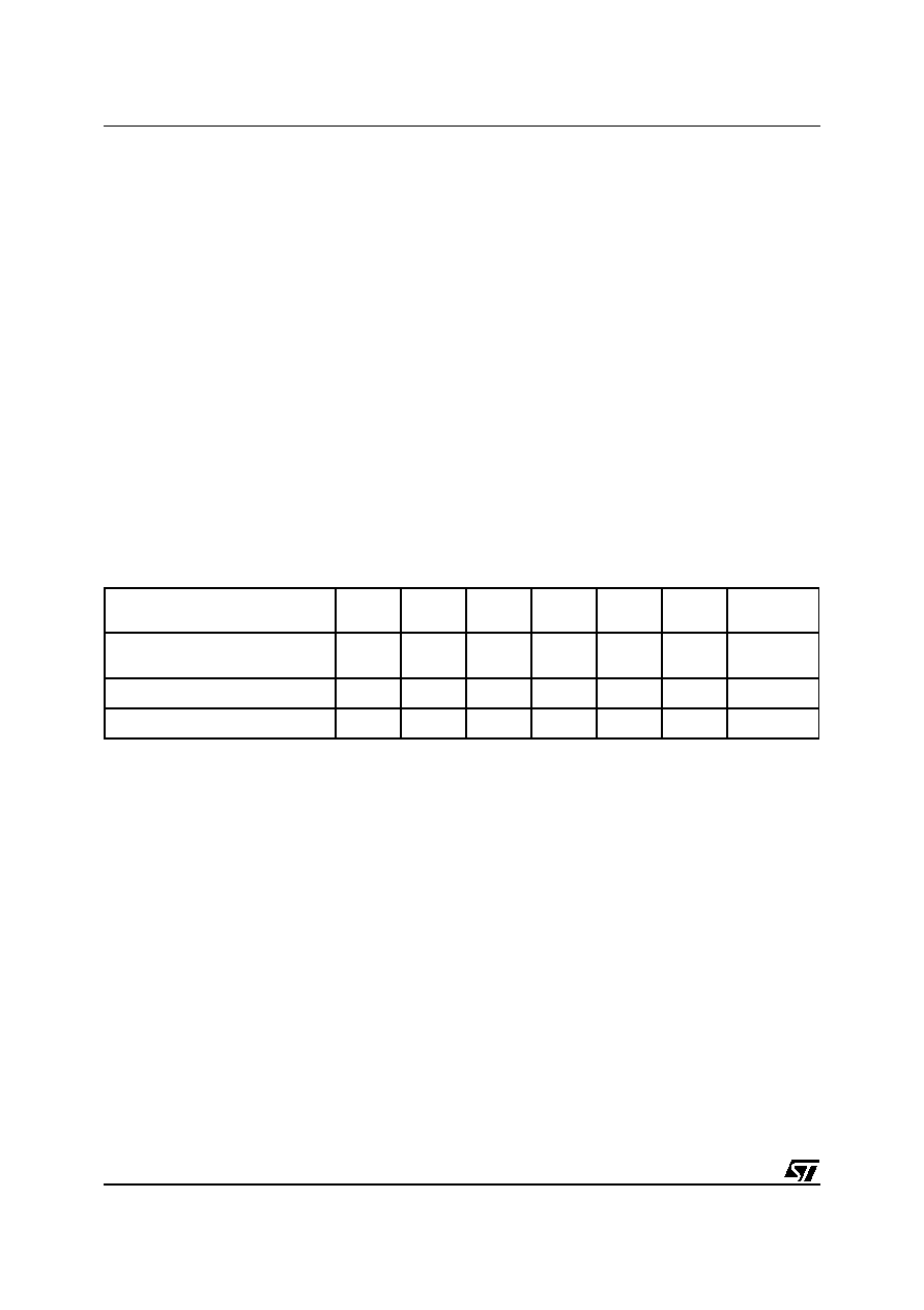
Table 14. Default Values
Note: 1. WDS, BMB0-BMB4, RB0, RB1.
2. State of other control bits undefined.
3. State of other control bits remains unchanged.
4. Assuming these bits set to '1' prior to power-down.
Condition
W
R
FT
AFE
ABE
SQWE
WATCHDOG
Register(1)
Initial Power-up
(Battery Attach for SNAPHAT)(2)
000000
0
RESET(3)
000000
0
Power-down(4)
000111
0
相關(guān)PDF資料 |
PDF描述 |
|---|---|
| M48T201Y-70MH6 | 1 TIMER(S), REAL TIME CLOCK, PDSO44 |
| M48T201Y-70MHTR | 1 TIMER(S), REAL TIME CLOCK, PDSO44 |
| M48T212V-70MH1 | 0 TIMER(S), REAL TIME CLOCK, PDSO44 |
| M48T212V-70MH6TR | 0 TIMER(S), REAL TIME CLOCK, PDSO44 |
| M48T212V-70MH6 | 0 TIMER(S), REAL TIME CLOCK, PDSO44 |
相關(guān)代理商/技術(shù)參數(shù) |
參數(shù)描述 |
|---|---|
| M48T201VMH | 制造商:STMICROELECTRONICS 制造商全稱:STMicroelectronics 功能描述:3.3V-5V TIMEKEEPER CONTROLLER |
| M48T201VSH | 制造商:STMICROELECTRONICS 制造商全稱:STMicroelectronics 功能描述:3.3V-5V TIMEKEEPER CONTROLLER |
| M48T201Y | 制造商:STMICROELECTRONICS 制造商全稱:STMicroelectronics 功能描述:3.3V-5V TIMEKEEPER CONTROLLER |
| M48T201Y_07 | 制造商:STMICROELECTRONICS 制造商全稱:STMicroelectronics 功能描述:5.0 or 3.3V TIMEKEEPER㈢ supervisor |
| M48T201Y_09 | 制造商:STMICROELECTRONICS 制造商全稱:STMicroelectronics 功能描述:5.0 or 3.3 V TIMEKEEPER? supervisor |
發(fā)布緊急采購(gòu),3分鐘左右您將得到回復(fù)。