- 您現(xiàn)在的位置:買賣IC網(wǎng) > PDF目錄359065 > M48T35AV-10MH6 (意法半導(dǎo)體) 256 Kbit 32Kb x8 TIMEKEEPER SRAM PDF資料下載
參數(shù)資料
| 型號: | M48T35AV-10MH6 |
| 廠商: | 意法半導(dǎo)體 |
| 英文描述: | 256 Kbit 32Kb x8 TIMEKEEPER SRAM |
| 中文描述: | 256千位的32KB的SRAM x8計時器 |
| 文件頁數(shù): | 11/19頁 |
| 文件大小: | 148K |
| 代理商: | M48T35AV-10MH6 |
11/19
M48T35AY, M48T35AV
Calibrating the Clock
The M48T35AY/35AV is driven by a quartz con-
trolled oscillator with a nominal frequency of
32,768Hz. The devices are tested not to exceed
35 ppm (parts per million) oscillator frequency er-
ror at 25°C, which equates to about ±1.53 minutes
per month. With the calibration bits properly set,
the accuracy of each M48T35AY/35AV improves
to better than ±4 ppm at 25°C.
The oscillation rate of any crystal changes with
temperature (see Figure 11). Most clock chips
compensate for crystal frequency and tempera-
ture shift error with cumbersome trim capacitors.
The M48T35AY/35AV design, however, employs
periodic counter correction. The calibration circuit
adds or subtracts counts from the oscillator divider
circuit at the divide by 256 stage, as shown in Fig-
ure 9. The number of times pulses are blanked
(subtracted, negative calibration) or split (added,
positive calibration) depends upon the value load-
ed into the five Calibration bits found in the Control
Register. Adding counts speeds the clock up, sub-
tracting counts slows the clock down.
The Calibration byte occupies the five lower order
bits (D4-D0) in the Control Register 7FF8h. These
bits can be set to represent any value between 0
and 31 in binary form. Bit D5 is a Sign bit; '1' indi-
cates positive calibration, '0' indicates negative
calibration. Calibration occurs within a 64 minute
cycle. The first 62 minutes in the cycle may, once
per minute, have one second either shortened by
128 or lengthened by 256 oscillator cycles. If a bi-
nary '1' is loaded into the register, only the first 2
minutes in the 64 minute cycle will be modified; if
a binary 6 is loaded, the first 12 will be affected,
and so on.
Therefore, each calibration step has the effect of
adding 512 or subtracting 256 oscillator cycles for
every 125,829,120 actual oscillator cycles, that is
+4.068 or –2.034 ppm of adjustment per calibra-
tion step in the calibration register. Assuming that
the oscillator is in fact running at exactly 32,768Hz,
each of the 31 increments in the Calibration byte
would represent +10.7 or –5.35 seconds per
month which corresponds to a total range of +5.5
or –2.75 minutes per month.
Two methods are available for ascertaining how
much calibration a given M48T35AY/35AV may
require. The first involves simply setting the clock,
letting it run for a month and comparing it to a
known accurate reference (like WWV broadcasts).
While that may seem crude, it allows the designer
to give the end user the ability to calibrate his clock
as his environment may require, even after the fi-
nal product is packaged in a non-user serviceable
enclosure.
All the designer has to do is provide a simple utility
that accesses the Calibration byte.
The second approach is better suited to a manu-
facturing environment, and involves the use of
some test equipment. When the Frequency Test
(FT) bit, the seventh-most significant bit in the Day
Register is set to a '1', and D7 of the Seconds Reg-
ister is a '0' (Oscillator Running), DQ0 will toggle at
512Hz during a read of the Seconds Register. Any
deviation from 512Hz indicates the degree and di-
rection of oscillator frequency shift at the test tem-
perature. For example, a reading of 512.01024Hz
would indicate a +20 ppm oscillator frequency er-
ror, requiring a –10 (WR001010) to be loaded into
the Calibration Byte for correction. Note that set-
ting or changing the Calibration Byte does not af-
fect the Frequency test output frequency.
The FT bit MUST be reset to '0' for normal clock
operations to resume. The FT bit is automatically
Reset on power-up.
For more information on calibration, see the Appli-
cation Note AN934 "TIMEKEEPER Calibration".
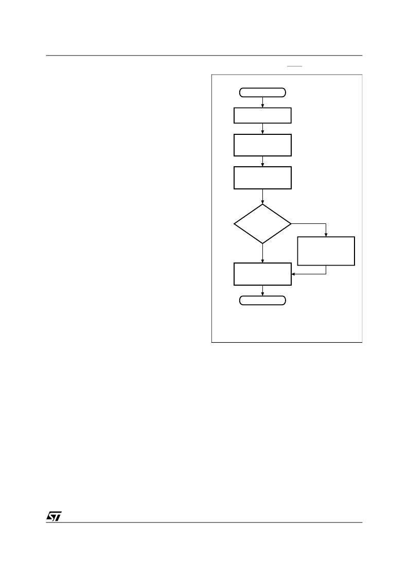
Figure 9. Checking the BOK Flag Status
READ DATA
AT ANY ADDRESS
AI00607
IS DATA
COMPLEMENT
OF FIRST
READ
(BATTERY OK)
POWER-UP
YES
NO
WRITE DATA
COMPLEMENT BACK
TO SAME ADDRESS
READ DATA
AT SAME
ADDRESS AGAIN
NOTIFY SYSTEM
OF LOW BATTERY
(DATA MAY BE
CORRUPTED)
WRITE ORIGINAL
DATA BACK TO
SAME ADDRESS
(BATTERY LOW)
CONTINUE
相關(guān)PDF資料 |
PDF描述 |
|---|---|
| M48T35AV-10MH1TR | 256 Kbit 32Kb x8 TIMEKEEPER SRAM |
| M48T35AV-10MH1 | ER 3C 3#12 PIN PLUG |
| M48T35AY-10MH6 | 256 Kbit 32Kb x8 TIMEKEEPER SRAM |
| M48T35AY-10MH1TR | 256 Kbit 32Kb x8 TIMEKEEPER SRAM |
| M48T35AVMH | 256 Kbit 32Kb x8 TIMEKEEPER SRAM |
相關(guān)代理商/技術(shù)參數(shù) |
參數(shù)描述 |
|---|---|
| M48T35AV-10MH6E | 功能描述:NVRAM 256K (32Kx8) 100ns BULK RoHS:否 制造商:Maxim Integrated 數(shù)據(jù)總線寬度:8 bit 存儲容量:1024 Kbit 組織:128 K x 8 接口類型:Parallel 訪問時間:70 ns 電源電壓-最大:5.5 V 電源電壓-最小:4.5 V 工作電流:85 mA 最大工作溫度:+ 70 C 最小工作溫度:0 C 封裝 / 箱體:EDIP 封裝:Tube |
| M48T35AV-10MH6F | 功能描述:NVRAM 256K (32Kx8) 100ns RoHS:否 制造商:Maxim Integrated 數(shù)據(jù)總線寬度:8 bit 存儲容量:1024 Kbit 組織:128 K x 8 接口類型:Parallel 訪問時間:70 ns 電源電壓-最大:5.5 V 電源電壓-最小:4.5 V 工作電流:85 mA 最大工作溫度:+ 70 C 最小工作溫度:0 C 封裝 / 箱體:EDIP 封裝:Tube |
| M48T35AV-10MH6TR | 制造商:STMICROELECTRONICS 制造商全稱:STMicroelectronics 功能描述:256 Kbit 32Kb x8 TIMEKEEPER SRAM |
| M48T35AV-10PC1 | 功能描述:NVRAM 256K (32Kx8) 100ns RoHS:否 制造商:Maxim Integrated 數(shù)據(jù)總線寬度:8 bit 存儲容量:1024 Kbit 組織:128 K x 8 接口類型:Parallel 訪問時間:70 ns 電源電壓-最大:5.5 V 電源電壓-最小:4.5 V 工作電流:85 mA 最大工作溫度:+ 70 C 最小工作溫度:0 C 封裝 / 箱體:EDIP 封裝:Tube |
| M48T35AV-10PC1 | 制造商:STMicroelectronics 功能描述:NVRAM Memory IC |
發(fā)布緊急采購,3分鐘左右您將得到回復(fù)。