- 您現(xiàn)在的位置:買賣IC網(wǎng) > PDF目錄370963 > M51996FP (Mitsubishi Electric Corporation) RADIATION HARDENED HIGH EFFICIENCY, 5 AMP SWITCHING REGULATORS PDF資料下載
參數(shù)資料
| 型號: | M51996FP |
| 廠商: | Mitsubishi Electric Corporation |
| 元件分類: | 基準電壓源/電流源 |
| 英文描述: | RADIATION HARDENED HIGH EFFICIENCY, 5 AMP SWITCHING REGULATORS |
| 中文描述: | 抗輻射高效,5安培開關(guān)穩(wěn)壓器 |
| 文件頁數(shù): | 17/22頁 |
| 文件大小: | 366K |
| 代理商: | M51996FP |

SWITCHING REGULATOR CONTROL
M51996AP/FP
MITSUBISHI (Dig./Ana. INTERFACE)
( / 22 )
17
Fig.25 shows the example circuit diagrams around the CLM+
terminal.It is required to connect the low pass filter,in order to
reduce the spike current component,as the main current or
drain current contains the spike current especially during the
turn-on duration of MOS-FIT.
1,000pF to 22,000pF is recommended for C
NF
and the R
NF1
and R
NF2
have the functions both to adjust the "current-
detecting-sensitivity" and to consist the low pass filter.
(1)Peripheral circuit of CLM+ terminal
Current limiting circuit
M51996A
GND
Vcc
Fig.25 Peripheral circuit diagram of CLM+ terminal
R1
Cvcc
INPUT
SMOOTHING
CAPACITOR
C
FIN
COLLECTOR
CLM+
V
OUT
EMITTER
C
NF
R
NF1
R
NF2
R
CLM
To design the R
NF1
and R
NF2
,it is required to consider the
influence of CLM+ terminal source current(I
INCLM
+),
which value is in the range of 90 to 270μA.
In order to be not influenced from these resistor paralleled value
of R
NF1
and R
NF2
,(R
NF1
/R
NF2
)is recommended to be less than
100
.
The R
CLM
should be the non-inductive resistor.
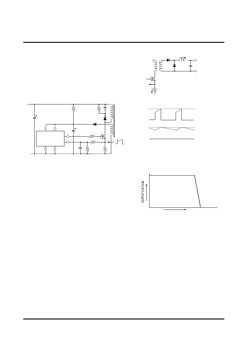
Fig.26 shows the primary and secondary current wave-forms
under the current limiting operation.
At the typical application of pulse by pulse primary current
detecting circuit,the secondary current depends on the primary
current.As the peak value of secondary current is limited to
specified value,the characteristics curve of output voltage
versus output current become to the one as shown in Fig.27.
(a)In case of feed forward system
(2)Over current limiting curve
I1
I2
R
CLM
CLM
Fig.26 Primary and secondary current waveforms
under the current limiting operation
condition on feed forward system
(a) Feed forward system
I
P1
I
P2
I1
I2
(b) Primary and secondary current
OUTPUT CURRENT
Fig.27 Over current limiting curve on feed forward
system
The demerit of the pulse by pulse current limiting system is that
the output pulse width can not reduce to less than some value
because of the delay time of low pass filter connected to the
CLM+ terminal and propagation delay time T
PDCLM
from CLM+
terminal to output terminal of type M51996A.The typical
T
PDCLM+
is 100ns.
As the frequency becomes higher,the delay time must be
shorter.And as the secondary output voltage becomes
higher,the dynamic range of on-duty must be wider;it means
that it is required to make the on-duration much more narrower.
So this system has the demerit at the higher oscillating
frequency and higher output voltage applications.
To prevent that the SOFT terminal is used to lower the
frequency when the curve starts to become vertical.
相關(guān)PDF資料 |
PDF描述 |
|---|---|
| M51997 | RADIATION HARDENED HIGH EFFICIENCY, 5 AMP SWITCHING REGULATORS |
| M51997FP | RADIATION HARDENED HIGH EFFICIENCY, 5 AMP SWITCHING REGULATORS |
| M51997P | RADIATION HARDENED HIGH EFFICIENCY, 5 AMP SWITCHING REGULATORS |
| M52001SP | SYNC SIGNAL PROCESSOR |
| M52003AFP | PAL VIDEO CHROMA INTERFACE |
相關(guān)代理商/技術(shù)參數(shù) |
參數(shù)描述 |
|---|---|
| M51996P | 制造商:MITSUBISHI 制造商全稱:Mitsubishi Electric Semiconductor 功能描述:M51996P |
| M51997 | 制造商:MITSUBISHI 制造商全稱:Mitsubishi Electric Semiconductor 功能描述:SWITCHING REGULATOR CONTROL |
| M51997FP | 制造商:MITSUBISHI 制造商全稱:Mitsubishi Electric Semiconductor 功能描述:SWITCHING REGULATOR CONTROL |
| M51997P | 制造商:Panasonic Industrial Company 功能描述:IC |
| M51998FP | 制造商:RENESAS 制造商全稱:Renesas Technology Corp 功能描述:SWITCHING REGULATOR CONTROL |
發(fā)布緊急采購,3分鐘左右您將得到回復(fù)。