- 您現(xiàn)在的位置:買賣IC網(wǎng) > PDF目錄385510 > M54617P (Mitsubishi Electric Corporation) LAN TRANSCEIVER PDF資料下載
參數(shù)資料
| 型號: | M54617P |
| 廠商: | Mitsubishi Electric Corporation |
| 英文描述: | LAN TRANSCEIVER |
| 中文描述: | 網(wǎng)絡收發(fā)器 |
| 文件頁數(shù): | 5/8頁 |
| 文件大小: | 116K |
| 代理商: | M54617P |
LAN TRANSCEIVER
M54617P
MITSUBISHI <CONTROL / DRIVER IC>
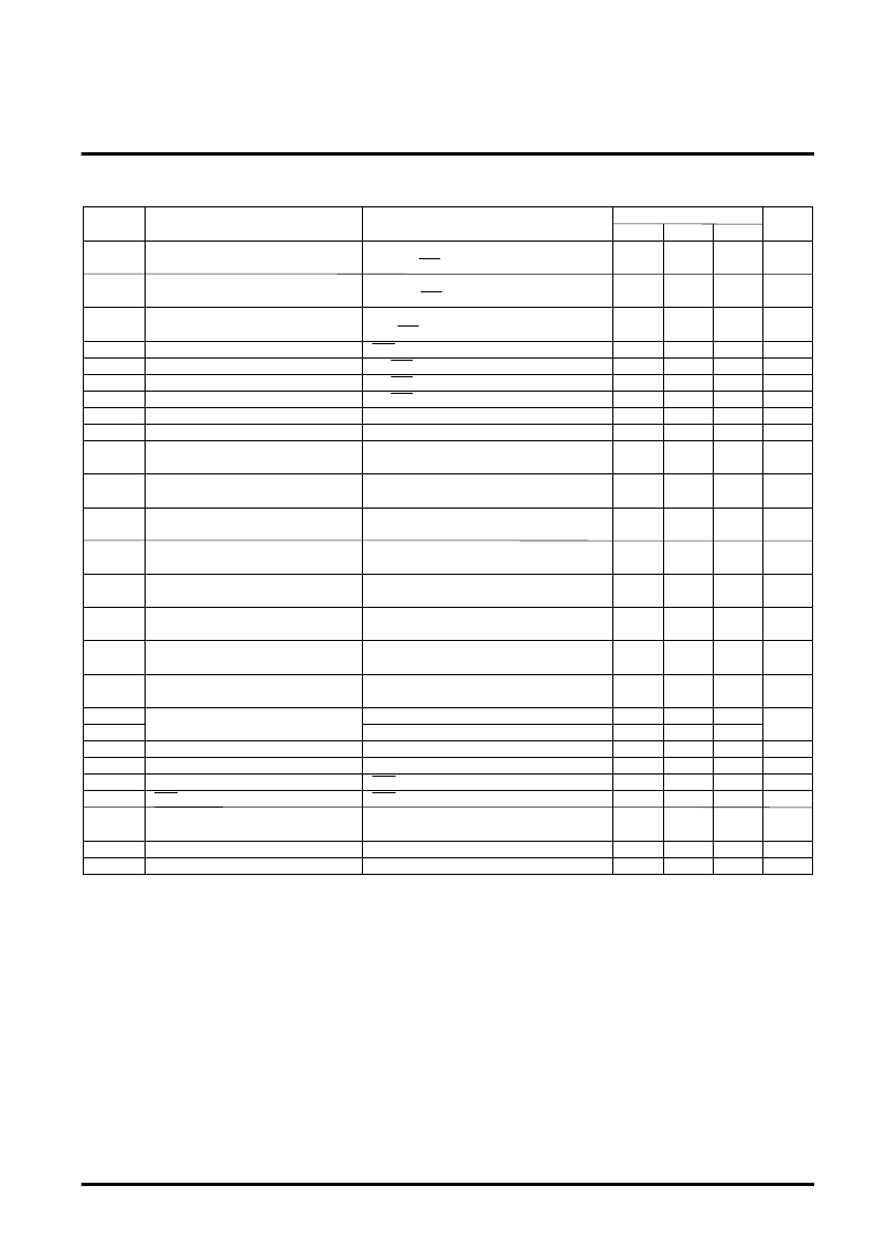
ELECTRICAL CHARACTERISTICS
(Ta = 25
°
C and V
DD
= 5.0V when in normal operation unless otherwise noted)
Symbol
Parameter
I
DD1
Limits
Typ.
Min.
Max.
Unit
5.0
mA
I
DD2
I
DD3
V
TH1
V
TH2
VTL
VHYSL
V
CIN
VHYSB
I
IPP1
I
IDP1
I
IPP2
I
IDP2
I
IPM1
I
IDM1
I
IPM2
I
IDM2
V
DROP1
V
DROP2
V
OH1
V
OL1
V
OH2
IPD
C
I1
C
I2
VTH1
Supply current 1
Supply current 2
Supply current 3
“H” input threshold voltage 1
“H” input threshold voltage 2
“L” input threshold voltage
Hysterisis width
BUS input voltage range
Input hysterisis width
BUS(+) leakage current 1
BUS(+) leakage current 2
BUS(+) leakage current 3
BUS(+) leakage current 4
BUS(-) leakage current 1
BUS(-) leakage current 2
BUS(-) leakage current 3
BUS(-) leakage current 4
Driver and drop voltage
“H” output voltage 1
“L” output voltage 1
“H” output voltage 2
ERR pulldown current
Input capacitance 1
Input capacitance 2
Grounding offset voltage
Conditions
RBUS = 105
,
T
X
= “L”, STB = “H”
RBUS = 105
,
T
X
= “H”, STB = “H”
RBUS = 105
,
T
X
= STB = “H”
ERR
T
X
, STB
T
X
, STB
T
X
, STB
BUS(+), BUS(-)
BUS(+) and BUS(-) differential input
When the power supply is turned OFF
(V
DD
= 0V), BUS(+) = 0V
When the power supply is turned OFF
(V
DD
= 0V), BUS(+) = 5V
When the power supply is turned ON
BUS(+) = 0V
When the power supply is turned ON
BUS(+) = 5V
When the power supply is turned OFF
(V
DD
= 0V), BUS(-) = 5V
When the power supply is turned OFF
(V
DD
= 0V), BUS(-) = 0V
When the power supply is turned ON
BUS(-) = 5V
When the power supply is turned ON
BUS(-) = 0V
IBUS(+) = -50mA
IBUS(-) = +50mA
R
X
pin I
OH
= -1mA
R
X
pin I
OL
= +1mA
ERR pin I
OH
= -1mA
ERR pin V
OH
= 3.0V
When the power supply is turned OFF
(V
DD
= 0V)
When the power supply is turned ON
Between 2 nodes
55
mA
200
μ
A
2.2
2.3
1.6
0.4
V
SS
70
3.2
3.5
2.8
1.0
V
V
V
V
V
V
DD
-2.0
300
mV
100
μ
A
100
μ
A
-20
μ
A
100
μ
A
100
μ
A
100
μ
A
20
μ
A
100
μ
A
1.5
0.6
5.0
0.6
5.0
700
V
4.5
V
V
V
μ
A
4.5
150
pF
150
0.5
pF
V
350
相關PDF資料 |
PDF描述 |
|---|---|
| M54640P | STEPPER MOTOR DRIVER |
| M55SP-1 | Stepping Motors |
| M56787FP | SPINDLE MOTOR DRIVER |
| M57716 | 430-450MHz 12.5V,17W,SSB MOBILE RADIO |
| M57716L | 360-380MHz, 12.5V, 13W, DIGITAL MOBILE RADIO |
相關代理商/技術參數(shù) |
參數(shù)描述 |
|---|---|
| M54640P | 制造商:RENESAS 制造商全稱:Renesas Technology Corp 功能描述:Stepper Motor Driver |
| M54640P(#TC0J) | 制造商:Renesas Electronics Corporation 功能描述: |
| M54641 | 制造商:MITSUBISHI 制造商全稱:Mitsubishi Electric Semiconductor 功能描述:Bi-DIRECTIONAL MOTOR DRIVER WITH BRAKE FUNCTION |
| M54641FP | 制造商:MITSUBISHI 制造商全稱:Mitsubishi Electric Semiconductor 功能描述:Bi-DIRECTIONAL MOTOR DRIVER WITH BRAKE FUNCTION |
| M54641L | 制造商:MITSUBISHI 制造商全稱:Mitsubishi Electric Semiconductor 功能描述:Bi-DIRECTIONAL MOTOR DRIVER WITH BRAKE FUNCTION |
發(fā)布緊急采購,3分鐘左右您將得到回復。