- 您現(xiàn)在的位置:買賣IC網(wǎng) > PDF目錄202012 > MA4E400H-906 SILICON, HIGH BARRIER SCHOTTKY, KU BAND, MIXER DIODE PDF資料下載
參數(shù)資料
| 型號(hào): | MA4E400H-906 |
| 元件分類: | 射頻混頻器 |
| 英文描述: | SILICON, HIGH BARRIER SCHOTTKY, KU BAND, MIXER DIODE |
| 封裝: | CASE 906, 4 PIN |
| 文件頁(yè)數(shù): | 2/3頁(yè) |
| 文件大小: | 83K |
| 代理商: | MA4E400H-906 |
M/A-COM, Inc.
North America:
Tel. (800) 366-2266
s
Asia/Pacific: Tel. +81 (03) 3226-1671
s
Europe: Tel.
+44 (1344) 869 595
Fax (800) 618-8883
Fax +81 (03) 3226-1451
Fax +44 (1344) 300 020
2
Specifications Subject to Change Without Notice.
V3.00
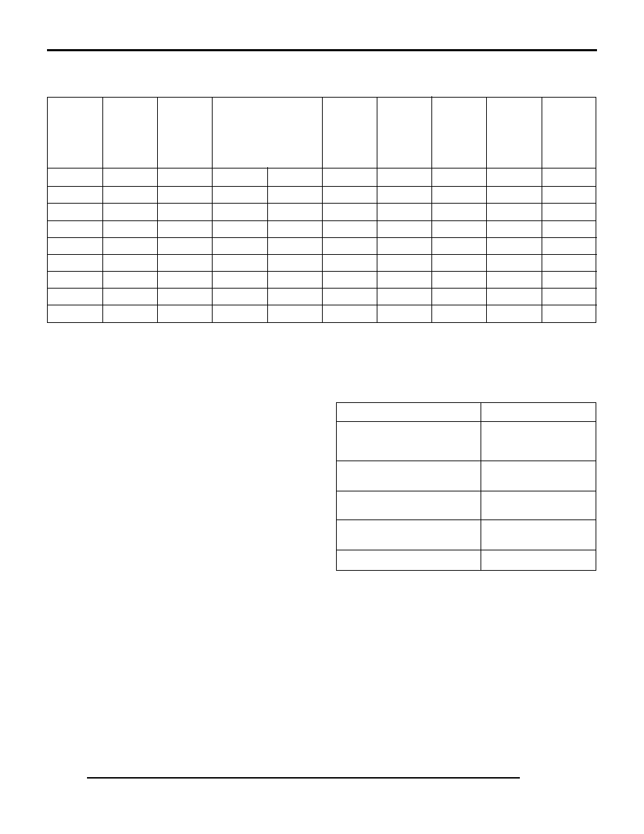
Absolute Maximum Ratings at 25°C
Electrical Specifications at 25°C
Maximum4
Maximum
Junction1,2
Junction
Typical4
Forward
Minimum 5
Capacitance
Maximum 3
Forward
Voltage
Reverse
C
j
Difference
Resistance
Voltage
Difference
Voltage
Model*
Barrier
Frequency
(pF)
C
j
R
T
V
F
V
F
V
R
Number
Height
Band
Min.
Max.
(pF)
(Ohms)
(Volts)
MA4E402L
Low
S
0.30
0.60
0.10
7
0.250
0.020
2.0
MA4E401L
Low
C X
0.15
0.40
0.10
10
0.270
0.020
2.0
MA4E400L
Low
Ku
0.05
0.25
0.05
12
0.300
0.020
2.0
MA4E402M
Medium
S
0.30
0.60
0.10
7
0.350
0.020
3.0
MA4E401M
Medium
C-X
0.15
0.40
0.10
10
0.370
0.020
3.0
MA4E400M
Medium
Ku
0.05
0.25
0.05
12
0.410
0.020
3.0
MA4E402H
High
S
0.30
0.60
0.10
7
0.550
0.020
5.0
MA4E401H
High
C-X
0.15
0.40
0.10
10
0.570
0.020
5.0
MA4E400H
High
Ku
0.05
0.25
0.05
12
0.610
0.020
5.0
Schottky Barrier Beam Lead and Packaged Bridge Quads
MA4E400 Series
Parameter
Absolute Maximum
Maximum Power Dissipation
(derate linearly to zero allowable
dissipation at 150°C)
75 mW/ junction
Operating and Storage
Temperature Range of Junctions
- 65°C to + 150°C
Plastic Packages
-65°C to +125°C
(Case Styles 227, 228, 963)
Ceramic Package
-65°C to +150°C
(Case Style 226)
Beam Strength
2g (Case Style 906)
* Case styles are specified by adding the case style number as a suffix to
the basic part number. For example, an MA4E402L-228 is a low barrier
bridge quad housed in the 228 case style. The available packages are
226, 227, 228 or 963. To order a beam lead part add “- 906”.
Notes:
1. C
j is measured across diagonal leads at VR = 0V and f = 1 MHz.
2. C
T = Cj + CP is the package capacitance.
3. Series resistance, R
S, is determined by subtracting the junction
resistance, Rj, from the measured value of 10 mA dynamic (slope)
resistance, RT:
R
S = RT - Rj Ohms
Junction resistance is computed from the following equation:
R
j = 26/1F Ohms
I
F is the forward bias current in mA.
4.
C
j is measured across adjacent quad leads at VR = 0V and
f = 1 MHz.
5. V
R is measured at IR = 10 A
Applications
These beam lead Schottky bridge quads are commonly
used in sampling and modulator applications. The small
case sizes and minimal electrical parasitics are well suited
for miniature broadband components.
High speed switching, a necessary sampling requirement,
is accomplished with the Schottky diode. Schottky diodes
have switching speeds in the picosecond range. The four
closely matched junctions assure high inherent isolation
between the signal and sampler pulse circuits.
The different barrier heights enable the designer to select
a diode with an appropriate barrier such that the RF sig-
nal input to the sampler will not cause the diodes in the
bridge to conduct. The diode circuit configuration is
shown on the next page.
相關(guān)PDF資料 |
PDF描述 |
|---|---|
| MMSZ5237C | 8.2 V, 0.5 W, SILICON, UNIDIRECTIONAL VOLTAGE REGULATOR DIODE |
| MA44652B-30 | K BAND, 20 GHz, SILICON, STEP RECOVERY DIODE |
| MA46483-186A | VHF-KA BAND, 6.8 pF, 22 V, GALLIUM ARSENIDE, HYPERABRUPT VARIABLE CAPACITANCE DIODE |
| MA4ST240-1141 | S BAND, 3.5 pF, 12 V, SILICON, HYPERABRUPT VARIABLE CAPACITANCE DIODE |
| MA46416-30 | VHF-KA BAND, 1.8 pF, 18 V, GALLIUM ARSENIDE, HYPERABRUPT VARIABLE CAPACITANCE DIODE |
相關(guān)代理商/技術(shù)參數(shù) |
參數(shù)描述 |
|---|---|
| MA4E5 | 制造商:EDAL 制造商全稱:EDAL 功能描述:SILICON GENERAL PURPOSE 3.0 AMP DIODES |
| MA4E514M4 | 制造商: 功能描述: 制造商:undefined 功能描述: |
| MA4E909 | 制造商:M/A-COM Technology Solutions 功能描述:MA4E909 |
| MA4E914-120 | 制造商:未知廠家 制造商全稱:未知廠家 功能描述:Ceramic Packaged Schottky Mixer Diodes |
| MA4E914-276 | 制造商:未知廠家 制造商全稱:未知廠家 功能描述:STRIPLINE PACKAGED SCHOTTKY MIXER DIODES |
發(fā)布緊急采購(gòu),3分鐘左右您將得到回復(fù)。