- 您現(xiàn)在的位置:買賣IC網(wǎng) > PDF目錄370994 > MAC15-4FP (MOTOROLA INC) ISOLATED TRIACs THYRISTORS 15 AMPERES RMS 200 thru 800 VOLTS PDF資料下載
參數(shù)資料
| 型號: | MAC15-4FP |
| 廠商: | MOTOROLA INC |
| 元件分類: | 晶閘管 |
| 英文描述: | ISOLATED TRIACs THYRISTORS 15 AMPERES RMS 200 thru 800 VOLTS |
| 中文描述: | 200 V, 15 A, TRIAC |
| 文件頁數(shù): | 2/4頁 |
| 文件大小: | 80K |
| 代理商: | MAC15-4FP |

3–64
Motorola Thyristor Device Data
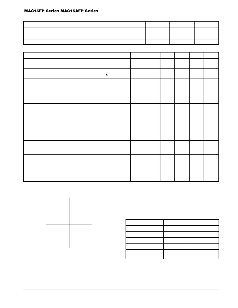
THERMAL CHARACTERISTICS
Characteristic
Symbol
Max
Unit
Thermal Resistance, Junction to Case
R
θ
JC
R
θ
CS
R
θ
JA
2
°
C/W
Thermal Resistance, Case to Sink
2.2 (typ)
°
C/W
Thermal Resistance, Junction to Ambient
60
°
C/W
ELECTRICAL CHARACTERISTICS
(TC = 25
°
C unless otherwise noted.)
Characteristic
Symbol
Min
Typ
Max
Unit
Peak Blocking Current (Either Direction) TJ = 25
°
C
(VD = Rated VDRM, TJ = 125
°
C, Gate Open)
IDRM
—
—
—
—
10
2
μ
A
mA
Peak On-State Voltage (Either Direction)
(ITM = 21 A Peak; Pulse Width = 1 to 2 ms, Duty Cycle
2%)
VTM
—
1.3
1.6
Volts
Gate Trigger Current (Continuous dc)
(Main Terminal Voltage = 12 Vdc, RL = 100 Ohms)
MT2(+), G(+)
MT2(+), G(–)
MT2(–), G(–)
MT2(–), G(+) “A” SUFFIX ONLY
IGT
—
—
—
—
—
—
—
—
50
50
50
75
mA
Gate Trigger Voltage (Continuous dc)
(Main Terminal Voltage = 12 Vdc, RL = 100 Ohms)
MT2(+), G(+)
MT2(+), G(–)
MT2(–), G(–)
MT2(–), G(+) “A” SUFFIX ONLY
(Main Terminal Voltage = Rated VDRM, RL = 10 k
, TJ = +110
°
C)
MT2(+), G(+); MT2(–), G(–); MT2(+), G(–)
MT2(–), G(+) “A” SUFFIX ONLY
VGT
—
—
—
—
0.2
0.2
0.9
0.9
1.1
1.4
—
—
2
2
2
2.5
—
—
Volts
Holding Current (Either Direction)
(Main Terminal Voltage = 12 Vdc, Gate Open,
Initiating Current = 200 mA)
IH
—
6
40
mA
Turn-On Time
(VD = Rated VDRM, ITM = 17 A, IGT = 120 mA,
Rise Time = 0.1
μ
s, Pulse Width = 2
μ
s)
tgt
—
1.5
—
μ
s
Critical Rate of Rise of Commutation Voltage
(VD = Rated VDRM, ITM = 21 A, Commutating di/dt = 7.6 A/ms,
Gate Unenergized, TC = 80
°
C)
dv/dt(c)
—
5
—
V/
μ
s
QUADRANT DEFINITIONS
QUADRANT II
QUADRANT I
QUADRANT III
QUADRANT IV
MT2(+)
MT2(–)
MT2(+), G(–)
MT2(+), G(+)
MT2(–), G(–)
MT2(–), G(+)
G(–)
G(+)
Trigger devices are recommended for gating on Triacs. They provide:
1. Consistent predictable turn-on points.
2. Simplified circuitry.
3. Fast turn-on time for cooler, more efficient and reliable operation.
ELECTRICAL CHARACTERISTICS of RECOMMENDED
BIDIRECTIONAL SWITCHES
Usage
General
Part Number
MBS4991
MBS4992
VS
IS
6–10 V
7.5–9 V
350
μ
A Max
120
μ
A Max
VS1–VS2
Temperature
Coefficient
0.5 V Max
0.2 V Max
0.02%/
°
C Typ
1. Ratings apply for open gate conditions. Thyristor devices shall not be tested with a constant current source for blocking capability such that the
voltage applied exceeds the rated blocking voltage.
相關(guān)PDF資料 |
PDF描述 |
|---|---|
| MAC15-6FP | ISOLATED TRIACs THYRISTORS 15 AMPERES RMS 200 thru 800 VOLTS |
| MAC15-8FP | ISOLATED TRIACs THYRISTORS 15 AMPERES RMS 200 thru 800 VOLTS |
| MAC15A10FP | ISOLATED TRIACs THYRISTORS 15 AMPERES RMS 200 thru 800 VOLTS |
| MAC15A6FP | ISOLATED TRIACs THYRISTORS 15 AMPERES RMS 200 thru 800 VOLTS |
| MAC15A8FP | ISOLATED TRIACs THYRISTORS 15 AMPERES RMS 200 thru 800 VOLTS |
相關(guān)代理商/技術(shù)參數(shù) |
參數(shù)描述 |
|---|---|
| MAC156 | 制造商:未知廠家 制造商全稱:未知廠家 功能描述:TRIAC|400V V(DRM)|15A I(T)RMS|TO-220 |
| MAC15-6 | 制造商:GESS 制造商全稱:GESS 功能描述:15-A Silicon Triacs |
| MAC156AFP | 制造商:未知廠家 制造商全稱:未知廠家 功能描述:TRIAC|400V V(DRM)|15A I(T)RMS|TO-220 |
| MAC156FP | 制造商:未知廠家 制造商全稱:未知廠家 功能描述:TRIAC|400V V(DRM)|15A I(T)RMS|TO-220 |
| MAC15-6FP | 制造商:MOTOROLA 制造商全稱:Motorola, Inc 功能描述:ISOLATED TRIACs THYRISTORS 15 AMPERES RMS 200 thru 800 VOLTS |
發(fā)布緊急采購,3分鐘左右您將得到回復(fù)。