- 您現(xiàn)在的位置:買賣IC網(wǎng) > PDF目錄383374 > MAX3901D (Maxim Integrated Products, Inc.) 150Mbps Automotive Fiber Optic Receivers PDF資料下載
參數(shù)資料
| 型號: | MAX3901D |
| 廠商: | Maxim Integrated Products, Inc. |
| 英文描述: | 150Mbps Automotive Fiber Optic Receivers |
| 中文描述: | 汽車亦可達(dá)150Mbps光纖接收機(jī) |
| 文件頁數(shù): | 3/13頁 |
| 文件大?。?/td> | 623K |
| 代理商: | MAX3901D |

M
150Mbps Automotive Fiber Optic Receiver
_______________________________________________________________________________________
3
PARAMETER
SYMBOL
R
STATUS
t
OP
t
STBY
CONDITION
MIN
10
TYP
16
0.2
16
MAX
24
0.5
100
UNIT
k
ms
μs
STATUS Resistance
Transition to operating mode (Note 5)
Transition to standby mode (Note 6)
Power-Detect Time
ELECTRICAL CHARACTERISTICS
—
MAX3901 (continued)
(V
CC
= +3.135V to +5.25V, C
PD
= 2pF; T
j
= -40
°
C to +140
°
C. Typical values are at V
CC
= +5.0V and T
A
= +25
°
C, unless otherwise noted.)
Note 1:
Guaranteed by design and characterization.
Note 2:
BER = 1E-9, biphase-coded data containing three consecutive, identical digits. Waveform shaped by 39MHz four-pole filter.
Note 3:
See Figure 1. V
TH
is 1.5V for the MAX3901, 0V for (AC-coupled) differential output from the MAX3902. Data is biphase-coded
with three consecutive, identical digits added. Data input to the MAX3901 is shaped by a 39MHz four-pole filter. Data input to
the MAX3902 is shaped by a 117MHz four-pole filter.
Maximum PWV = MAX [t1
max
, t2
max
- 1UI, t3
max
- 2UI].
Minimum PWV = MIN [t1
min
, t2
min
- 1UI, t3
min
- 2UI].
Minimum PWD = MIN [(t
n-max
+ t
n-min
-2 x n x UI)/2], where n = 1, 2, 3.
Maximum PWD = MAX [(t
n-max
+ t+
n-min
-2 x n x UI)/2], where n = 1, 2, 3.
Note 4:
Data-dependent jitter is measured as shown in
MOST Specification of Physical Layer,
Version 1.1, data rate = 45Mbps.
Note 5:
Time from I
IN
> I
STL
to STATUS = low, C
STATUS
< 10pF.
Note 6:
Time from I
IN
< I
STH
to STATUS = high, C
STATUS
< 10pF.
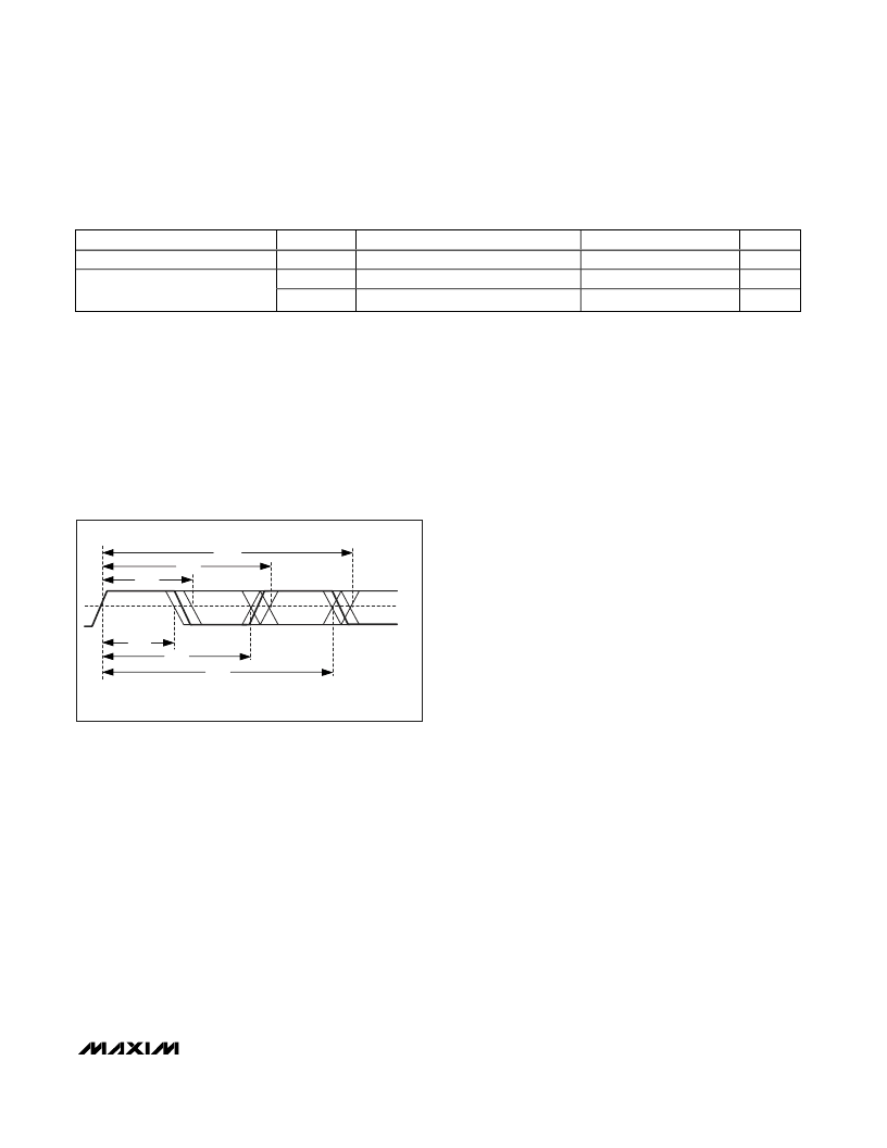
TRIGGER ON RISING EDGE
V
TH
t
3max
t
2max
t
1max
t
1min
t
2min
t
3min
Figure 1. PWV and PWD Timing Diagrams
相關(guān)PDF資料 |
PDF描述 |
|---|---|
| MAX3901-MAX3902 | 150Mbps Automotive Fiber Optic Receivers |
| MAX3901 | 150Mbps Automotive Fiber Optic Receivers |
| MAX3902E | 150Mbps Automotive Fiber Optic Receivers |
| MAX3901E | 150Mbps Automotive Fiber Optic Receivers |
| MAX3902 | 150Mbps Automotive Fiber Optic Receivers |
相關(guān)代理商/技術(shù)參數(shù) |
參數(shù)描述 |
|---|---|
| MAX3901E/D DIE | 制造商:Maxim Integrated Products 功能描述: |
| MAX3901E/D-B0Q WAF | 制造商:Maxim Integrated Products 功能描述: |
| MAX3901EVKIT | 制造商:Maxim Integrated Products 功能描述: |
| MAX3902E/D DIE | 制造商:Maxim Integrated Products 功能描述: |
| MAX3902EVKIT | 制造商:Maxim Integrated Products 功能描述: |
發(fā)布緊急采購,3分鐘左右您將得到回復(fù)。