- 您現(xiàn)在的位置:買賣IC網(wǎng) > PDF目錄383412 > MAX4589EPP (MAXIM INTEGRATED PRODUCTS INC) Low-Voltage, High-Isolation, Dual 2-Channel RF/Video Multiplexer PDF資料下載
參數(shù)資料
| 型號(hào): | MAX4589EPP |
| 廠商: | MAXIM INTEGRATED PRODUCTS INC |
| 元件分類: | 運(yùn)動(dòng)控制電子 |
| 英文描述: | Low-Voltage, High-Isolation, Dual 2-Channel RF/Video Multiplexer |
| 中文描述: | 2-CHANNEL, VIDEO MULTIPLEXER, PDIP20 |
| 封裝: | 0.300 INCH, PLASTIC, MO-058AB, MS-001AE, DIP-20 |
| 文件頁(yè)數(shù): | 10/20頁(yè) |
| 文件大?。?/td> | 309K |
| 代理商: | MAX4589EPP |
第1頁(yè)第2頁(yè)第3頁(yè)第4頁(yè)第5頁(yè)第6頁(yè)第7頁(yè)第8頁(yè)第9頁(yè)當(dāng)前第10頁(yè)第11頁(yè)第12頁(yè)第13頁(yè)第14頁(yè)第15頁(yè)第16頁(yè)第17頁(yè)第18頁(yè)第19頁(yè)第20頁(yè)
M
Low-Voltage, High-Isolation,
Dual 2-Channel RF/Video Multiplexer
10
______________________________________________________________________________________
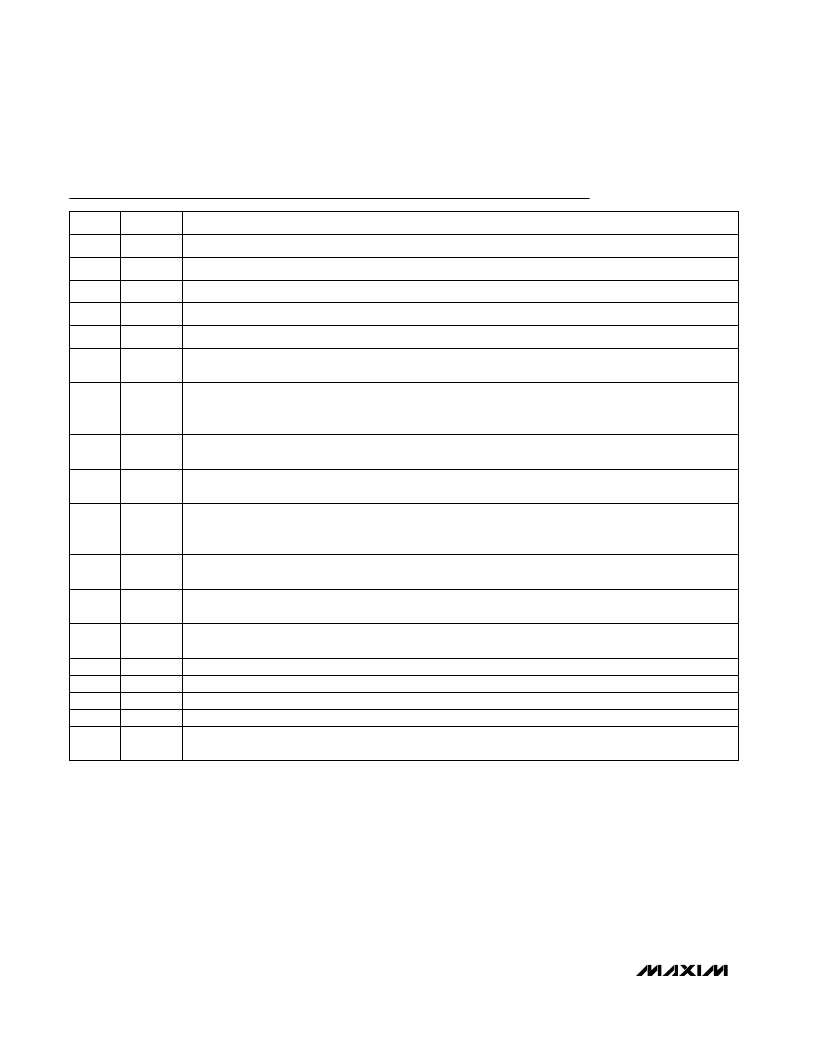
Pin Desc ription
Interface Select Input. Drive low for parallel data interface operation. Drive high for serial data interface
operation and to enable the DOUT driver.
SER/
PAR
20
Analog Switch Common Terminal. See Truth Tables.
COM2
19
Analog Negative Supply Voltage Input. Connect to GND for single-supply operation.
V-
18
Normally Open Analog Input Terminal. See Truth Tables.
NO3
17
Normally Open Analog Input Terminal. See Truth Tables.
NO4
15
Logic Supply Input. Powers the DOUT driver and other digital circuitry. V
L
sets both the input threshold
levels and the output logic levels.
V
L
14
In parallel mode this pin is the transparent Latch Enable. In the serial mode, this pin is the Chip-Select input.
See Truth Tables.
LE
/
CS
9
In parallel mode, A1/SCLK is the most significant address bit. If 2/
4
is high, A1/SCLK is ignored. In the serial
mode, A1/SCLK is the serial shift clock input. Data is loaded on the rising edge of SCLK. See Truth Tables.
A1/SCLK
10
In parallel mode, this pin is the least significant address bit. In serial mode, DOUT is the output from the
internal 4-bit shift register. DOUT is intended for daisy-chain cascading. DOUT is not three-stated by
CS
.
See Serial Operation
A0/DOUT
11
Switch Enable. Drive EN low to force all channels off. Drive high to allow normal multiplexer operation.
Operates asynchronously in serial mode. In parallel mode, EN is latched when the
LE
signal is high.
EN
12
Serial Data Input. In serial mode, data is loaded on the rising edge of SCLK. Connect to V
L
or GND in
parallel mode.
DIN
13
Normally Open Analog Input Terminal. See Truth Tables.
NO2
6
Multiplexer Configuration Control. Connect to V
L
to select dual 2-channel mode. Connect to GND for single
4-channel multiplexer operation. See Truth Tables.
2/
4
7
Active-Low Reset Input. In serial mode, drive
RS
low to force the latches and shift registers to the power-on
reset state and force all switches open. In parallel mode, drive
RS
low to force the latches to the power-on
reset state and force switches open. See Truth Tables.
RS
8
Normally Open Analog Input Terminal. See Truth Tables.
NO1
4
Analog Positive Supply Voltage Input
V+
3
PIN
Analog Switch Common Terminal. See Truth Tables.
COM1
2
Ground. Connect to ground plane. See Grounding section.
GND
1, 5, 16
FUNCTION
NAME
相關(guān)PDF資料 |
PDF描述 |
|---|---|
| MAX4589EAP | Low-Voltage, High-Isolation, Dual 2-Channel RF/Video Multiplexer |
| MAX4589EWP | Low-Voltage, High-Isolation, Dual 2-Channel RF/Video Multiplexer |
| MAX458CPL | 8x4 Video Crosspoint Switches with Buffers |
| MAX458-MAX459 | 8x4 Video Crosspoint Switches with Buffers |
| MAX458EPL | 8x4 Video Crosspoint Switches with Buffers |
相關(guān)代理商/技術(shù)參數(shù) |
參數(shù)描述 |
|---|---|
| MAX4589EWP | 功能描述:視頻開關(guān) IC RoHS:否 制造商:Texas Instruments 開關(guān)數(shù)量:4 開啟電阻(最大值):12 Ohms 傳播延遲時(shí)間: 開啟時(shí)間(最大值): 關(guān)閉時(shí)間(最大值): 最大工作溫度:+ 85 C 最小工作溫度:- 40 C 封裝 / 箱體:WQFN-42 封裝:Reel |
| MAX4589EWP-T | 功能描述:視頻開關(guān) IC RoHS:否 制造商:Texas Instruments 開關(guān)數(shù)量:4 開啟電阻(最大值):12 Ohms 傳播延遲時(shí)間: 開啟時(shí)間(最大值): 關(guān)閉時(shí)間(最大值): 最大工作溫度:+ 85 C 最小工作溫度:- 40 C 封裝 / 箱體:WQFN-42 封裝:Reel |
| MAX458CPL | 功能描述:視頻開關(guān) IC RoHS:否 制造商:Texas Instruments 開關(guān)數(shù)量:4 開啟電阻(最大值):12 Ohms 傳播延遲時(shí)間: 開啟時(shí)間(最大值): 關(guān)閉時(shí)間(最大值): 最大工作溫度:+ 85 C 最小工作溫度:- 40 C 封裝 / 箱體:WQFN-42 封裝:Reel |
| MAX458CQH | 制造商:Maxim Integrated Products 功能描述:- Rail/Tube |
| MAX458CQH+D | 功能描述:視頻開關(guān) IC RoHS:否 制造商:Texas Instruments 開關(guān)數(shù)量:4 開啟電阻(最大值):12 Ohms 傳播延遲時(shí)間: 開啟時(shí)間(最大值): 關(guān)閉時(shí)間(最大值): 最大工作溫度:+ 85 C 最小工作溫度:- 40 C 封裝 / 箱體:WQFN-42 封裝:Reel |
發(fā)布緊急采購(gòu),3分鐘左右您將得到回復(fù)。