- 您現(xiàn)在的位置:買賣IC網(wǎng) > PDF目錄383445 > MAX5942A-MAX5942B (Maxim Integrated Products, Inc.) Octal D-Type Positive Edge Triggered Flip-Flops with 3-State Outputs 20-CFP -55 to 125 PDF資料下載
參數(shù)資料
| 型號: | MAX5942A-MAX5942B |
| 廠商: | Maxim Integrated Products, Inc. |
| 英文描述: | Octal D-Type Positive Edge Triggered Flip-Flops with 3-State Outputs 20-CFP -55 to 125 |
| 中文描述: | IEEE 802.3af功率以太網(wǎng)接口/ PWM控制器的功率器件 |
| 文件頁數(shù): | 13/24頁 |
| 文件大小: | 465K |
| 代理商: | MAX5942A-MAX5942B |
IEEE 802.3af Power-Over-Ethernet
Interface/PWM Controller for Power Devices
______________________________________________________________________________________
13
M
The PSE determines the class of a PD by applying a volt-
age at the PD input and measures the current sourced
out of the PSE. When the PSE applies a voltage between
12.6V and 20V, the MAX5942A/MAX5942B exhibit a cur-
rent characteristic with values indicated in Table 2. The
PSE uses the classification current information to classify
the power requirement of the PD. The classification cur-
rent includes the current drawn by the 25.5k
detection
signature resistor and the supply current of the
MAX5942A/MAX5942B so that the total current drawn by
the PD is within the IEEE 802.3af standard figures. The
classification current is turned off whenever the device is
in power mode.
Power Mode
During power mode, when V
IN
rises above the undervolt-
age lockout threshold (V
UVLO,ON
), the MAX5942A/
MAX5942B gradually turn on the internal N-channel MOS-
FET Q1 (see Figure 2). The MAX5942A/MAX5942B
charge the gate of Q1 with a constant current source
(10μA, typ). The drain-to-gate capacitance of Q1 limits
the voltage rise rate at the drain of MOSFET, thereby limit-
ing the inrush current. To reduce the inrush current, add
external drain-to-gate capacitance (see the
Inrush
Current
section). When the drain of Q1 is within 1.2V of its
source voltage and its gate-to-source voltage is above
5V, the MAX5942A/MAX5942B assert the PGOOD/
PGOOD
outputs. The MAX5942A/MAX5942B have a wide
UVLO hysteresis and turn-off deglitch time to compensate
for the high impedance of the twisted-pair cable.
Undervoltage Lockout
The MAX5942A/MAX5942B operate up to a 67V supply
voltage with a default UVLO turn-on set at 39V and a
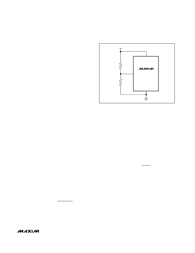
UVLO turn-off set at 30V. Adjust the UVLO threshold
using a resistor-divider connected to UVLO (see Figure
3). When the input voltage is above the UVLO threshold
(V
UVLO,ON
), the IC is in power mode and the MOSFET is
on. When the input voltage goes below the UVLO thresh-
old (V
UVLO,OFF
) for more than t
OFF_DLY
, the MOSFET
turns off.
To adjust the UVLO threshold, connect an external
resistor-divider from GND to UVLO and from UVLO to
V
EE
. Use the following equations to calculate R1 and
R2 for a desired UVLO threshold:
R1 = 25.5k
- R2
where V
IN,EX
is the desired UVLO threshold. Since the
resistor-divider replaces the 25.5k
PD detection resis-
tor, ensure that the sum of R1 and R2 equals 25.5k
±1%. When using the external resistor-divider, the
MAX5942 has an external reference voltage hysteresis of
20% (typ). In other words, when UVLO is programmed
externally, the turn-off threshold will be 80% (typ) of the
new UVLO turn-on threshold.
Inrush Current Limit
The MAX5942A/MAX5942B charge the gate of the inter-
nal MOSFET with a constant current source (10μA, typ).
The drain-to-gate capacitance of the MOSFET limits the
voltage rise rate at the drain, thereby limiting the inrush
current. Add an external capacitor from GATE to OUT
to further reduce the inrush current. Use the following
equation to calculate the inrush current:
The recommended inrush current for a PoE application
is 100mA.
PGOOD/
PGOOD
Outputs
PGOOD is an open-drain, active-high logic output.
PGOOD goes high impedance when V
OUT
is within 1.2V
of V
EE
and when GATE is 5V above V
EE
. Otherwise,
PGOOD is pulled to V
OUT
(given that V
OUT
is at least 5V
below GND). Connect PGOOD to SS_
SHDN
to enable
the PWM controller.
PGOOD
is an open-drain, active-low logic output.
PGOOD
is pulled to V
EE
when V
OUT
is within 1.2V of V
EE
and when GATE is 5V above V
EE
. Otherwise,
PGOOD
goes high impedance.
I
I
x
C
C
INRUSH
G
OUT
GATE
=
R
k
xV
V
REF UVLO
INEX
,
2
25 5
=
.
,
R1
UVLO
GND
V
EE
R2
V
IN
= 24V TO 60V
MAX5942A
MAX5942B
Figure 3. Setting Undervoltage Lockout with an External
Resistor-Divider
相關(guān)PDF資料 |
PDF描述 |
|---|---|
| MAX5942BCSE | Quadruple 2-Input Positive-NAND Buffers With Open-Collector Outp 14-CDIP -55 to 125 |
| MAX5946 | Dual PCI Express, Hot-Plug Controller |
| MAX5946AETX | Dual PCI Express, Hot-Plug Controller |
| MAX5946LETX | Dual PCI Express, Hot-Plug Controller |
| MAX6002EUR | IC-SM-2.5V VOLTAGE REFERENCE |
相關(guān)代理商/技術(shù)參數(shù) |
參數(shù)描述 |
|---|---|
| MAX5942BCSE | 功能描述:電源開關(guān) IC - POE / LAN RoHS:否 制造商:Fairchild Semiconductor 開關(guān)數(shù)量:Single 開關(guān)配置:SPST 開啟電阻(最大值):7.3 Ohms 串話: 帶寬: 開啟時間(最大值):13 ns 關(guān)閉時間(最大值):20 ns 切換電壓(最大): 工作電源電壓:8 V to 26 V 最大工作溫度:+ 125 C 安裝風格:Through Hole 封裝 / 箱體:TO-220F-6 |
| MAX5942BCSE+ | 功能描述:輸入/輸出控制器接口集成電路 IEEE 802.3af POE Int/PWM Controller RoHS:否 制造商:Silicon Labs 產(chǎn)品: 輸入/輸出端數(shù)量: 工作電源電壓: 最大工作溫度:+ 85 C 最小工作溫度:- 40 C 安裝風格:SMD/SMT 封裝 / 箱體:QFN-64 封裝:Tray |
| MAX5942BCSE+T | 功能描述:輸入/輸出控制器接口集成電路 IEEE 802.3af POE Int/PWM Controller RoHS:否 制造商:Silicon Labs 產(chǎn)品: 輸入/輸出端數(shù)量: 工作電源電壓: 最大工作溫度:+ 85 C 最小工作溫度:- 40 C 安裝風格:SMD/SMT 封裝 / 箱體:QFN-64 封裝:Tray |
| MAX5942BCSE-T | 功能描述:電源開關(guān) IC - POE / LAN RoHS:否 制造商:Fairchild Semiconductor 開關(guān)數(shù)量:Single 開關(guān)配置:SPST 開啟電阻(最大值):7.3 Ohms 串話: 帶寬: 開啟時間(最大值):13 ns 關(guān)閉時間(最大值):20 ns 切換電壓(最大): 工作電源電壓:8 V to 26 V 最大工作溫度:+ 125 C 安裝風格:Through Hole 封裝 / 箱體:TO-220F-6 |
| MAX5942BESE | 功能描述:電源開關(guān) IC - POE / LAN RoHS:否 制造商:Fairchild Semiconductor 開關(guān)數(shù)量:Single 開關(guān)配置:SPST 開啟電阻(最大值):7.3 Ohms 串話: 帶寬: 開啟時間(最大值):13 ns 關(guān)閉時間(最大值):20 ns 切換電壓(最大): 工作電源電壓:8 V to 26 V 最大工作溫度:+ 125 C 安裝風格:Through Hole 封裝 / 箱體:TO-220F-6 |
發(fā)布緊急采購,3分鐘左右您將得到回復(fù)。