- 您現(xiàn)在的位置:買賣IC網(wǎng) > PDF目錄385542 > MAX6667AUT-T (Maxim Integrated Products, Inc.) High-Accuracy PWM Output Temperature Sensors PDF資料下載
參數(shù)資料
| 型號: | MAX6667AUT-T |
| 廠商: | Maxim Integrated Products, Inc. |
| 元件分類: | 溫度/濕度傳感器 |
| 英文描述: | High-Accuracy PWM Output Temperature Sensors |
| 中文描述: | 高精度PWM輸出溫度傳感器 |
| 文件頁數(shù): | 5/8頁 |
| 文件大小: | 268K |
| 代理商: | MAX6667AUT-T |
Detailed Description
The MAX6666/MAX6667 are high-accuracy, low-cost,
low current (200μA typ) temperature sensors ideal for
interfacing with μCs or μPs. The MAX6666/MAX6667
convert the ambient temperature into a ratiometric
PWM output at a nominal frequency of 35Hz (±20%) at
+25
°
C.
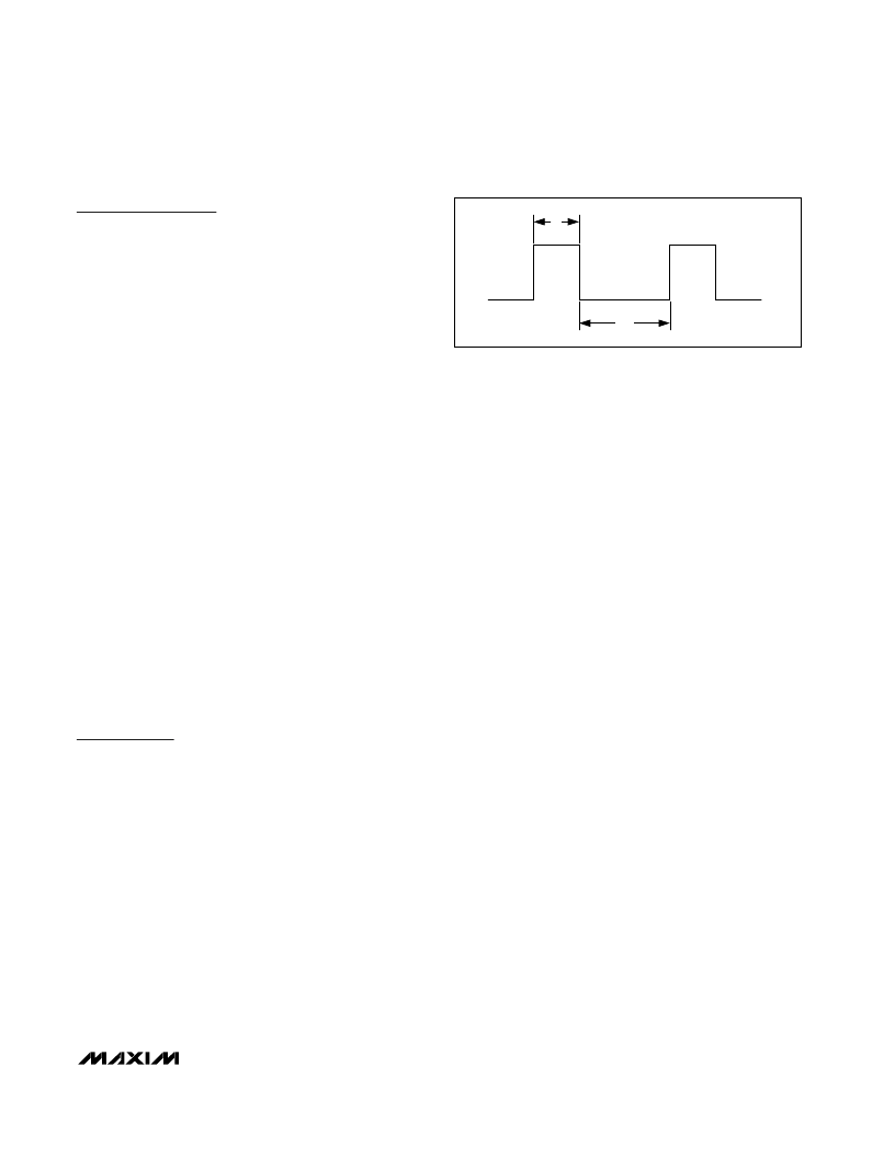
The time periods, t
1
(high) and t
2
(low) (Figure 1), are
easily read by the μP
’
s timer/counter port. To calculate
the temperature, use the expression below:
Temperature (
°
C) = +235 - (400 x t
1
) / t
2
The μC or μP measures the output of the MAX6666/
MAX6667 by counting t
1
and t
2
and computing the
temperature based on their ratio. The resolution of the
count is a function of the processor clock frequency
and the resolution of the counter. The MAX6666/
MAX6667 have a resolution of approximately 11 bits.
Always use the same clock for t
1
and t
2
counters so
that the temperature is strictly based on a ratio of the
two times, thus eliminating errors due to different
clocks
’
frequencies.
The MAX6666 (Figure 2a) has a push-pull output and
provides Rail-to Rail
output drive. The ability to source
and sink current allows the MAX6666 to drive capaci-
tive loads up to 10nF with less than 1
°
C error.
The MAX6667 (Figure 2b) has an open-drain output.
The output capacitance should be minimized in
MAX6667 applications because the sourcing current is
set by the pullup resistor. If the output capacitance
becomes too large, lengthy rise and fall times distort
the pulse width, resulting in inaccurate measurements.
Applications Information
Accurate temperature monitoring requires a good ther-
mal contact between the MAX6666/MAX6667 and the
object being monitored. A precise temperature mea-
surement depends on the thermal resistance between
the object being monitored and the MAX6666 die. Heat
flows in and out of plastic packages primarily through
the leads. For the best thermal contact, connect all
unused pins to ground. If the sensor is intended to
measure the temperature of a heat-generating compo-
nent on the circuit board, mount the device as close as
possible to that component and share the ground
traces (if they are not too noisy) with the component.
This maximizes the heat transfer from the component to
the sensor.
Power-Supply Bypassing
The MAX6666/MAX6667 operate from a +3V to +5.5V
supply. If a noisy power-supply line is used, bypass
V
CC
to GND with a 0.1μF capacitor.
Power Supply from μP Port Pin
The low quiescent current of the MAX6666/MAX6667
enables it to be powered from a logic line, which meets
the requirements for supply voltage range. This pro-
vides a simple shutdown function to totally eliminate
quiescent current by taking the logic line low. The logic
line must be able to withstand the 0.1μF power-supply
bypass capacitance.
Galvanic Isolation
Use an optocoupler to isolate the MAX6666/MAX6667
whenever a high common-mode voltage is present.
Because some optocouplers have turn-off times that
are much longer than their turn-on times, choose an
optocoupler with equal turn-on and turn-off times.
Unequal turn-on/turn-off times produce an error in the
temperature reading.
Thermal Considerations
Self-heating may cause the temperature measurement
accuracy of the MAX6666/MAX6667 to degrade in
some applications. The quiescent dissipation and the
power dissipated by the digital output may cause
errors in obtaining the accurate temperature measure-
ment. The temperature errors depend on the thermal
conductivity of the package (SOT23, 140
°
C/W; 8-pin
SO, 170
°
C/W; 8-pin μMAX, 242
°
C/W), the mounting
technique, and the airflow. Static dissipation in the
MAX6666/MAX6667 is typically 4.5mW operating at 5V
with no load. As a worst-case example, consider the
MAX6667 and its maximum rated load of 5mA and
assume a maximum output voltage of 0.8V adds 4mW
power dissipation. In an 8-pin μMAX, this would result
in a temperature rise of 0.004
242 or approximately
M
High-Accuracy PWM Output Temperature
Sensors
_______________________________________________________________________________________
5
Rail-to-Rail is a registered trademark of Nippon Motorola, Ltd.
t
2
t
1
Figure 1. MAX6666/MAX6667 PWM Output
相關(guān)PDF資料 |
PDF描述 |
|---|---|
| MAX6666 | 3-Line To 8-Line Decoder/Demultiplexer 20-LCCC -55 to 125 |
| MAX6666ASA | 3-Line To 8-Line Decoder/Demultiplexer 16-CDIP -55 to 125 |
| MAX6666AUA | 3-Line To 8-Line Decoder/Demultiplexer 16-CFP -55 to 125 |
| MAX6667ASA | High-Accuracy PWM Output Temperature Sensors |
| MAX6667AUA | High-Accuracy PWM Output Temperature Sensors |
相關(guān)代理商/技術(shù)參數(shù) |
參數(shù)描述 |
|---|---|
| MAX6668AUA040 | 制造商:Maxim Integrated Products 功能描述:REMOTE TEMPERATURE SWITCHES WITH INTEGRATED F - Bulk |
| MAX6668AUA045 | 制造商:Maxim Integrated Products 功能描述:REMOTE TEMPERATURE SWITCHES WITH INTEGRATED F - Bulk |
| MAX6668AUA050 | 制造商:Maxim Integrated Products 功能描述:REMOTE TEMPERATURE SWITCHES WITH INTEGRATED F - Bulk |
| MAX6668AUA40 | 功能描述:板上安裝溫度傳感器 RoHS:否 制造商:Omron Electronics 輸出類型:Digital 配置: 準確性:+/- 1.5 C, +/- 3 C 溫度閾值: 數(shù)字輸出 - 總線接口:2-Wire, I2C, SMBus 電源電壓-最大:5.5 V 電源電壓-最小:4.5 V 最大工作溫度:+ 50 C 最小工作溫度:0 C 關(guān)閉: 安裝風格: 封裝 / 箱體: 設(shè)備功能:Temperature and Humidity Sensor |
| MAX6668AUA40+ | 制造商:Rochester Electronics LLC 功能描述: 制造商:Maxim Integrated Products 功能描述: |
發(fā)布緊急采購,3分鐘左右您將得到回復。