- 您現(xiàn)在的位置:買賣IC網(wǎng) > PDF目錄1946 > MAX9950DCCB+TD (Maxim Integrated Products)IC PMU DUAL 64TQFP PDF資料下載
參數(shù)資料
| 型號(hào): | MAX9950DCCB+TD |
| 廠商: | Maxim Integrated Products |
| 文件頁數(shù): | 11/23頁 |
| 文件大?。?/td> | 0K |
| 描述: | IC PMU DUAL 64TQFP |
| 標(biāo)準(zhǔn)包裝: | 750 |
| 系列: | * |

MAX9949/MAX9950
Dual Per-Pin Parametric Measurement Units
______________________________________________________________________________________
19
determines whether the MAX9949/MAX9950 force cur-
rent or voltage. The other switch determines whether the
MSR_ output senses the DUT current or DUT voltage.
Independent control of these switches and the
HI-ZFORCE state permits flexible modes of operation
beyond the traditional force-voltage/measure-current
(FVMI) and force-current/measure-voltage (FIMV)
modes. The MAX9949/MAX9950 support the following
five modes:
FVMI
FIMV
FVMV
FIMI
FNMV
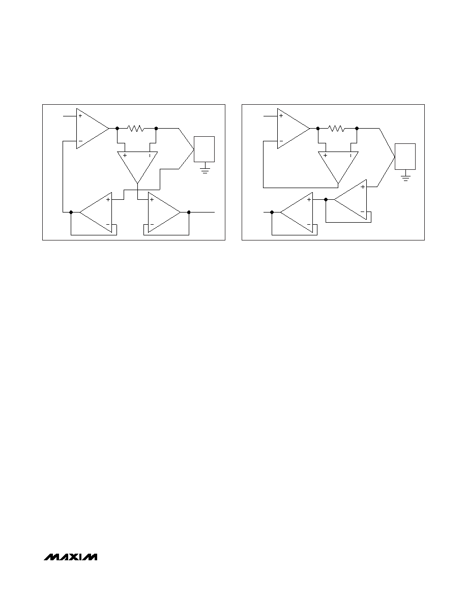
Figure 6 shows the internal path structure for force-volt-
age/measure-current mode. In force-voltage/measure-
current mode, the current across the appropriate
external sense resistor (R_A to R_E) provides a voltage
to the MSR_ output. The SENSE_ input samples the
voltage at the DUT and feeds the buffered result back
to the negative input of the voltage amplifier. The volt-
age at MSR_ is proportional to the FORCE_ current in
accordance with the following formula:
VMSR_ = IFORCE_ x RSENSE x 2
Figure 7 shows the internal path structure for the force-
current/measure-voltage mode. In force-current/mea-
sure-voltage mode, the appropriate external sense
resistor (R_A to R_E) provides a feedback voltage to
the inverting input of the voltage amplifier. The SENSE_
input samples the voltage at the DUT and provides a
buffered result at the MSR_ output.
High-Z States
The FORCE_, MSR_, and comparator outputs feature
individual high-Z control that places them into a high-
impedance, low-leakage state. The high-Z state allows
busing of MSR_ and comparator outputs with other
PMU measure and comparator outputs. The FORCE_
output high-Z state allows for additional modes of oper-
ation as described in Table 5 and can eliminate the
need for a series relay in some applications.
The FORCE_, MSR_, and comparator outputs power up
in the high-Z state.
Input Source Selection and Gating
Either one of two input signals, IN0_ or IN1_, can control
both the forced voltage and the forced current. In this
case, the two input signals represent alternate forcing
values that can be selected with the serial interface.
Alternatively, each input signal can be dedicated to con-
trol a single forcing function (i.e., voltage or current).
Ground, DUT Ground, IOS
The MAX9949/MAX9950 utilize two local grounds,
AGND (analog ground) and DGND (digital ground).
Connect AGND and DGND together on the PC board.
In a typical ATE system, the PMU force voltage is rela-
tive to the DUT ground. In this case, reference the input
voltages IN0_ and IN1_ to the DUT ground. Similarly,
reference IOS to the DUT ground. If it is not desired to
offset the current control and measure voltages, con-
nect IOS to the DUT ground potential.
Reference the MSR_ output to the DUT ground.
Figure 6. Force-Voltage/Measure-Current Functional Diagram
Figure 7. Force-Current/Measure-Voltage Functional Diagram
IN1_
MSR_
AV = +2
DUT
DUTGND
FORCE_
SENSE_
RSENSE
IN1_
AV = +2
DUT
DUTGND
MSR_
FORCE_
SENSE_
RSENSE
相關(guān)PDF資料 |
PDF描述 |
|---|---|
| MAX9952FCCB+T | IC PMU DUAL 64TQFP |
| MAXQ2000-RAX+ | IC MCU 32K FLASH 68-QFN |
| MAXQ2010-RFX+ | IC MCU 16BIT 64KB FLASH 100-LQFP |
| MAXQ3120-FFN+ | IC MCU 32KB FLASH 80-MQFP |
| MAXQ3210-EMX+ | IC MCU 16BIT LP 24-DIP |
相關(guān)代理商/技術(shù)參數(shù) |
參數(shù)描述 |
|---|---|
| MAX9950FCCB | 制造商:Rochester Electronics LLC 功能描述: 制造商:Maxim Integrated Products 功能描述: |
| MAX9950FCCB+ | 功能描述:接口 - 專用 RoHS:否 制造商:Texas Instruments 產(chǎn)品類型:1080p60 Image Sensor Receiver 工作電源電壓:1.8 V 電源電流:89 mA 最大功率耗散: 最大工作溫度:+ 85 C 安裝風(fēng)格:SMD/SMT 封裝 / 箱體:BGA-59 |
| MAX9950FCCB+D | 制造商:Maxim from Components Direct 功能描述:MAXIM MAX9950FCCB+D INTERFACE - Trays 制造商:Maxim 功能描述:Maxim MAX9950FCCB+D Interface |
| MAX9950FCCB+T | 功能描述:接口 - 專用 RoHS:否 制造商:Texas Instruments 產(chǎn)品類型:1080p60 Image Sensor Receiver 工作電源電壓:1.8 V 電源電流:89 mA 最大功率耗散: 最大工作溫度:+ 85 C 安裝風(fēng)格:SMD/SMT 封裝 / 箱體:BGA-59 |
| MAX9950FCCB-D | 功能描述:接口 - 專用 RoHS:否 制造商:Texas Instruments 產(chǎn)品類型:1080p60 Image Sensor Receiver 工作電源電壓:1.8 V 電源電流:89 mA 最大功率耗散: 最大工作溫度:+ 85 C 安裝風(fēng)格:SMD/SMT 封裝 / 箱體:BGA-59 |
發(fā)布緊急采購(gòu),3分鐘左右您將得到回復(fù)。