- 您現(xiàn)在的位置:買賣IC網(wǎng) > PDF目錄377930 > MB90MF408PF (FUJITSU LTD) 16-Bit Original Microcontroller PDF資料下載
參數(shù)資料
| 型號: | MB90MF408PF |
| 廠商: | FUJITSU LTD |
| 元件分類: | 微控制器/微處理器 |
| 英文描述: | 16-Bit Original Microcontroller |
| 中文描述: | 16-BIT, FLASH, 16 MHz, MICROCONTROLLER, PQFP100 |
| 封裝: | 0.65 MM PITCH, PLASTIC, QFP-100 |
| 文件頁數(shù): | 8/64頁 |
| 文件大小: | 310K |
| 代理商: | MB90MF408PF |
第1頁第2頁第3頁第4頁第5頁第6頁第7頁當前第8頁第9頁第10頁第11頁第12頁第13頁第14頁第15頁第16頁第17頁第18頁第19頁第20頁第21頁第22頁第23頁第24頁第25頁第26頁第27頁第28頁第29頁第30頁第31頁第32頁第33頁第34頁第35頁第36頁第37頁第38頁第39頁第40頁第41頁第42頁第43頁第44頁第45頁第46頁第47頁第48頁第49頁第50頁第51頁第52頁第53頁第54頁第55頁第56頁第57頁第58頁第59頁第60頁第61頁第62頁第63頁第64頁

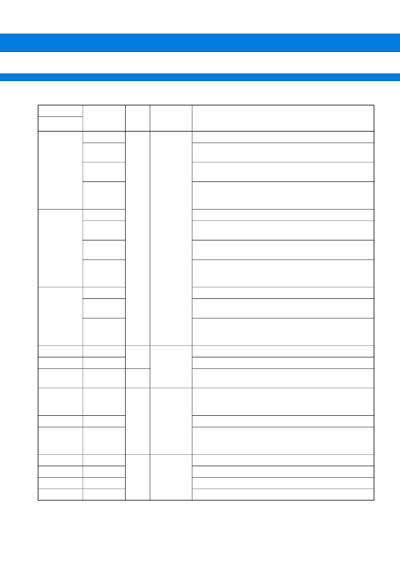
MB90M405 Series
8
(Continued)
Pin No.
Pin Name
Cir-
cuit
Type
State/
Function at
Reset
Description
QFP-100
76
PB4
F
Analog input
I/O port
AN12
Ch 12 of A/D converter analog input pin
Effective when analog input setting enabled (set with ADER)
SC2
Serial clock I/O pin for serial I/O ch 2
Effective when serial clock output for serial I/O ch 2 enabled
TIN0
External clock input pin of reload timer ch 0
Effective when external clock input enabled (ADER is priori-
tized)
78
PB5
I/O port
AN13
Ch 13 of A/D converter analog input pin
Effective when analog input setting enabled (set with ADER)
SO2
Serial data output pin for serial I/O ch 2
Effective when serial data output for serial I/O ch 2 enabled
TO0
External event output pin of reload timer ch 0
Effective when external event output enabled (ADER is pri-
oritized)
79, 80
PB6, PB7
I/O port
AN14, AN15
Ch 14 and ch 15 of A/D converter analog input pin
Effective when analog input setting enabled (set with ADER)
INT2, INT3
External interrupt input ch 2 and ch 3 are external factor input
pins
Accepted when bits EN2 and EN3 set to enabled
62
AV
CC
H
Power input
Vcc power input pin of analog macro
63
AV
SS
Vss power input pin of analog macro
48
V
KK
Power pin of pull-down side during high voltage resistant out-
put
49
MD0
B
Mode pins
Input pin for specifying operating mode. Connect to V
CC
.
Additionally, when flash boot program is being used, be sure
to switch to V
SS
.
50
MD1
Input pin for specifying operating mode. Connect to V
CC
.
51
MD2
Input pin for specifying operating mode. Connect to V
SS
.
Additionally, when flash boot program is being used, be sure
to switch to V
CC
.
11, 42
V
SS
IO
V
DD
FIP
V
SS
CPU
V
CC
CPU
Power input
I/O power (0 V : GND) input pin
23
FIP power (3 V : V
CC
) input pin
81
Control circuit power (0 V : GND) input pin
84
Control circuit power (3 V : V
CC
) input pin
相關(guān)PDF資料 |
PDF描述 |
|---|---|
| MB90P214A | 8-Bit Proprietary Microcontroller(8位專用微控制器) |
| MB90214 | 8-Bit Proprietary Microcontroller(8位專用微控制器) |
| MB90P214B | 8-Bit Proprietary Microcontroller(8位專用微控制器) |
| MB90V210 | 8-Bit Proprietary Microcontroller(8位專用微控制器) |
| MB90W214A | 8-Bit Proprietary Microcontroller(8位專用微控制器) |
相關(guān)代理商/技術(shù)參數(shù) |
參數(shù)描述 |
|---|---|
| MB90V340A-102CR | 制造商:FUJITSU 功能描述: |
| MB-910 | 制造商:Circuit Test 功能描述:BREADBOARD WIRING KIT - 350 PCS |
| MB9100100 | 制造商:COM/DUO 功能描述:FAN 4-6WKS |
| MB9100-100 | 制造商:COM/DUO 功能描述:FAN 4-6WKS |
| MB91101 | 制造商:Panasonic Industrial Company 功能描述:IC |
發(fā)布緊急采購,3分鐘左右您將得到回復(fù)。