- 您現(xiàn)在的位置:買(mǎi)賣(mài)IC網(wǎng) > PDF目錄377930 > MB90W224BZF (FUJITSU LTD) 16-bit Proprietary Microcontroller PDF資料下載
參數(shù)資料
| 型號(hào): | MB90W224BZF |
| 廠商: | FUJITSU LTD |
| 元件分類(lèi): | 微控制器/微處理器 |
| 英文描述: | 16-bit Proprietary Microcontroller |
| 中文描述: | 16-BIT, UVPROM, 16 MHz, MICROCONTROLLER, CQFP120 |
| 封裝: | CERAMIC, QFP-120 |
| 文件頁(yè)數(shù): | 45/105頁(yè) |
| 文件大?。?/td> | 1731K |
| 代理商: | MB90W224BZF |
第1頁(yè)第2頁(yè)第3頁(yè)第4頁(yè)第5頁(yè)第6頁(yè)第7頁(yè)第8頁(yè)第9頁(yè)第10頁(yè)第11頁(yè)第12頁(yè)第13頁(yè)第14頁(yè)第15頁(yè)第16頁(yè)第17頁(yè)第18頁(yè)第19頁(yè)第20頁(yè)第21頁(yè)第22頁(yè)第23頁(yè)第24頁(yè)第25頁(yè)第26頁(yè)第27頁(yè)第28頁(yè)第29頁(yè)第30頁(yè)第31頁(yè)第32頁(yè)第33頁(yè)第34頁(yè)第35頁(yè)第36頁(yè)第37頁(yè)第38頁(yè)第39頁(yè)第40頁(yè)第41頁(yè)第42頁(yè)第43頁(yè)第44頁(yè)當(dāng)前第45頁(yè)第46頁(yè)第47頁(yè)第48頁(yè)第49頁(yè)第50頁(yè)第51頁(yè)第52頁(yè)第53頁(yè)第54頁(yè)第55頁(yè)第56頁(yè)第57頁(yè)第58頁(yè)第59頁(yè)第60頁(yè)第61頁(yè)第62頁(yè)第63頁(yè)第64頁(yè)第65頁(yè)第66頁(yè)第67頁(yè)第68頁(yè)第69頁(yè)第70頁(yè)第71頁(yè)第72頁(yè)第73頁(yè)第74頁(yè)第75頁(yè)第76頁(yè)第77頁(yè)第78頁(yè)第79頁(yè)第80頁(yè)第81頁(yè)第82頁(yè)第83頁(yè)第84頁(yè)第85頁(yè)第86頁(yè)第87頁(yè)第88頁(yè)第89頁(yè)第90頁(yè)第91頁(yè)第92頁(yè)第93頁(yè)第94頁(yè)第95頁(yè)第96頁(yè)第97頁(yè)第98頁(yè)第99頁(yè)第100頁(yè)第101頁(yè)第102頁(yè)第103頁(yè)第104頁(yè)第105頁(yè)
45
MB90220 Series
6. PWC (Pulse Width Count) Timer
The PWC (pulse width count) timer is a 16-bit multifunction up-count timer with an input-signal pulse-width count
function and a reload timer function. The hardware configuration of this module is a 16-bit up-count timer, an
input pulse divider with divide ratio control register, four count input pins, and a 16-bit control register. Using
these components, the PWC timer provides the following features:
Timer functions:
An interrupt request can be generated at set time intervals.
Pulse signals synchronized with the timer cycle can be output.
The reference internal clock can be selected from among three internal clocks.
The time between arbitrary pulse input events can be counted.
The reference internal clock can be selected from among three internal clocks.
Various count modes:
“H” pulse width (
↑
to
↓
)/“L” pulse width (
↓
to
↑
)
Rising-edge cycle (
↑
to
↑
/Falling-edge cycle (
↓
to
↓
)
Count between edges (
↑
or
↓
to
↓
or
↑
)
Cycle count can be performed by 2
2n
division (n = 1, 2, 3, 4) of the input
pulse, with an 8 bit input divider.
An interrupt request can be generated once counting has been performed.
The number of times counting is to be performed (once or subsequently) can
be selected.
Pulse-width count functions:
The MB90220 series has four channels for this module.
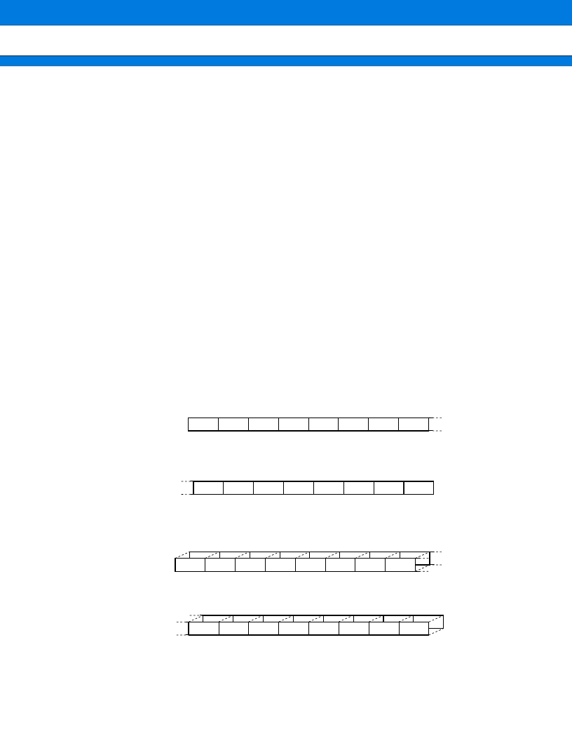
(1) Register Configuration
bit15
STRT
bit14
STOP
bit13
EDIR
bit12
EDIE
bit11
OVIR
bit10
OVIE
bit9
ERR
POUT
bit8
000051
H
000053
H
000055
H
000057
H
bit7
CKS1
bit6
CKS0
bit5
PIS1
bit4
PIS0
bit3
S/C
bit2
MOD1
bit1
MOD1
MOD0
bit0
000050
H
000052
H
000054
H
000056
H
001F01
H
001F03
H
001F05
H
001F07
H
001F00
H
001F02
H
001F04
H
001F06
H
PWCSR0
PWCSR1
PWCSR2
PWCSR3
00000000
B
PWCSR0
PWCSR1
PWCSR2
PWCSR3
00000000
B
PWCR0
PWCR1
PWCR2
PWCR3
00000000
B
PWCR0
PWCR1
PWCR2
PWCR3
00000000
B
bit7
bit6
bit5
bit4
bit3
bit2
bit1
bit0
Register name Address
Register name Address
Register name Address
Register name Address
(R/W)
(R/W)
(R)
(R/W)
(R/W)
(R/W)
(R)
(R/W)
Initial value
Initial value
Initial value
Initial value
bit15
bit14
bit13
bit12
bit11
bit10
bit9
bit8
(R/W)
(R/W)
(R/W)
(R/W)
(R/W)
(R/W)
(R/W)
(R/W)
(R/W)
(R/W)
(R/W)
(R/W)
(R/W)
(R/W)
(R/W)
(R/W)
(R/W)
(R/W)
(R/W)
(R/W)
(R/W)
(R/W)
(R/W)
(R/W)
PWC Control Status Register 0 to 3 (PWCSR0 to PWCSR3)
PWC Data Buffer Register 0 to 3 (PWCR0 to PWCR3)
相關(guān)PDF資料 |
PDF描述 |
|---|---|
| MB90W224ZF | 16-bit Proprietary Microcontroller |
| MB90V220 | 16-bit Proprietary Microcontroller |
| MB90V220CR | 16-bit Proprietary Microcontroller |
| MB90223PF | 16-bit Proprietary Microcontroller |
| MB90224 | 16-bit Proprietary Microcontroller |
相關(guān)代理商/技術(shù)參數(shù) |
參數(shù)描述 |
|---|---|
| MB-910 | 制造商:Circuit Test 功能描述:BREADBOARD WIRING KIT - 350 PCS |
| MB9100100 | 制造商:COM/DUO 功能描述:FAN 4-6WKS |
| MB9100-100 | 制造商:COM/DUO 功能描述:FAN 4-6WKS |
| MB91101 | 制造商:Panasonic Industrial Company 功能描述:IC |
| MB91101A | 制造商:FUJITSU 制造商全稱(chēng):Fujitsu Component Limited. 功能描述:32-bit RISC Microcontroller |
發(fā)布緊急采購(gòu),3分鐘左右您將得到回復(fù)。