- 您現(xiàn)在的位置:買賣IC網(wǎng) > PDF目錄377947 > MBM29LV002BC-70PNS (FUJITSU LTD) 2M (256K x 8) BIT PDF資料下載
參數(shù)資料
| 型號(hào): | MBM29LV002BC-70PNS |
| 廠商: | FUJITSU LTD |
| 元件分類: | DRAM |
| 英文描述: | 2M (256K x 8) BIT |
| 中文描述: | 256K X 8 FLASH 3V PROM, 70 ns, PDSO40 |
| 封裝: | PLASTIC, SON-40 |
| 文件頁數(shù): | 23/52頁 |
| 文件大?。?/td> | 436K |
| 代理商: | MBM29LV002BC-70PNS |
第1頁第2頁第3頁第4頁第5頁第6頁第7頁第8頁第9頁第10頁第11頁第12頁第13頁第14頁第15頁第16頁第17頁第18頁第19頁第20頁第21頁第22頁當(dāng)前第23頁第24頁第25頁第26頁第27頁第28頁第29頁第30頁第31頁第32頁第33頁第34頁第35頁第36頁第37頁第38頁第39頁第40頁第41頁第42頁第43頁第44頁第45頁第46頁第47頁第48頁第49頁第50頁第51頁第52頁
23
MBM29LV002TC
-70/-90/-12
/MBM29LV002BC
-70/-90/-12
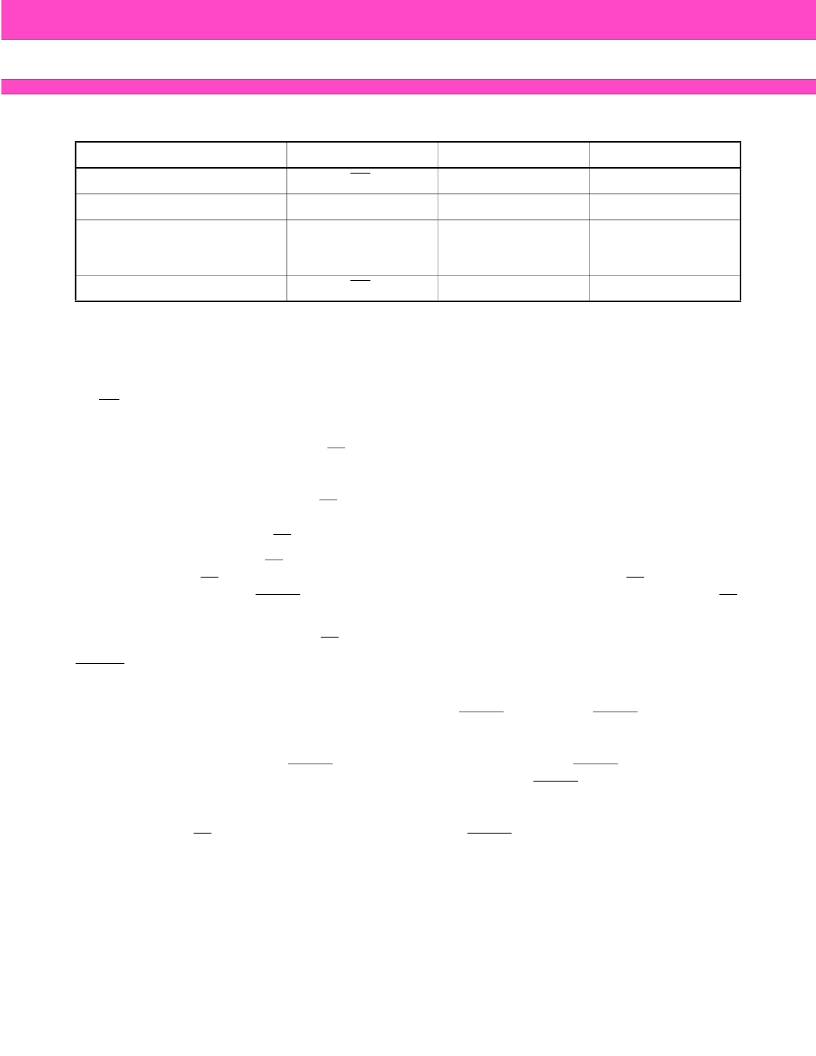
Notes:
1. Performing successive read operations from any address will cause DQ
6
to toggle.
2. Reading the byte address being programmed while in the erase-suspend program mode will indicate
logic “1” at the DQ
2
bit. However, successive reads from the erase-suspended sector will cause DQ
2
to
toggle.
RY/BY
Ready/Busy
The MBM29LV002TC/BC provide a RY/BY open-drain output pin as a way to indicate to the host system that
the Embedded Algorithms are either in progress or has been completed. If the output is low, the devices are
busy with either a program or erase operation. If the output is high, the devices are ready to accept any read/
write or erase operation. When the RY/BY pin is low, the devices will not accept any additional program or erase
commands with the exception of the Erase Suspend command. If the MBM29LV002TC/BC are placed in an
Erase Suspend mode, the RY/BY output will be high, by means of connecting with a pull-up resister to V
CC
.
During programming, the RY/BY pin is driven low after the rising edge of the fourth write pulse. During an erase
operation, the RY/BY pin is driven low after the rising edge of the sixth write pulse. The RY/BY pin will indicate
a busy condition during the RESET pulse. Refer to Figure 11 and 12 for a detailed timing diagram. The RY/BY
pin is pulled high in standby mode.
Since this is an open-drain output, RY/BY pins can be tied together in parallel with a pull-up resistor to V
CC
.
RESET
Hardware Reset
The MBM29LV002TC/BC devices may be reset by driving the RESET pin to V
IL
. The RESET pin has a pulse
requirement and has to be kept low (V
IL
) for at least 500 ns in order to properly reset the internal state machine.
Any operation in the process of being executed will be terminated and the internal state machine will be reset
to the read mode 20
μ
s after the RESET pin is driven low. Furthermore, once the RESET pin goes high, the
devices require an additional t
RH
before it will allow read access. When the RESET pin is low, the devices will
be in the standby mode for the duration of the pulse and all the data output pins will be tri-stated. If a hardware
reset occurs during a program or erase operation, the data at that particular location will be corrupted. Please
note that the RY/BY output signal should be ignored during the RESET pulse. See Figure 12 for the timing
diagram. Refer to Temporary Sector Unprotection for additional functionality.
If hardware reset occurs during Embedded Erase Algorithm, there is a possibility that the erasing sector(s)
cannot be used.
Mode
DQ
7
DQ
6
DQ
2
Program
DQ
7
Toggle
1
Erase
0
Toggle
Toggle
Erase-Suspend Read
(Erase-Suspended Sector)
(Note 1)
1
1
Toggle
Erase-Suspend Program
DQ
7
Toggle (Note 1)
1 (Note 2)
相關(guān)PDF資料 |
PDF描述 |
|---|---|
| MBM29LV002TC-70PNS | 2M (256K x 8) BIT |
| MBM29LV002TC-70PTN | 2M (256K x 8) BIT |
| MBM29LV002TC-70PTR | 2M (256K x 8) BIT |
| MBM29LV002TC-90 | 2M (256K x 8) BIT |
| MBM29LV002B | CMOS 2M (256K ×8) Flash Memory(CMOS 2M(256K ×8)位 單5V 電源電壓閃速存儲(chǔ)器) |
相關(guān)代理商/技術(shù)參數(shù) |
參數(shù)描述 |
|---|---|
| MBM29LV002BC-70PTN | 制造商:FUJITSU 制造商全稱:Fujitsu Component Limited. 功能描述:2M (256K x 8) BIT |
| MBM29LV002BC-70PTR | 制造商:FUJITSU 制造商全稱:Fujitsu Component Limited. 功能描述:2M (256K x 8) BIT |
| MBM29LV002BC-90 | 制造商:FUJITSU 制造商全稱:Fujitsu Component Limited. 功能描述:2M (256K x 8) BIT |
| MBM29LV002BC-90PNS | 制造商:FUJITSU 制造商全稱:Fujitsu Component Limited. 功能描述:2M (256K x 8) BIT |
| MBM29LV002BC-90PTN | 制造商:FUJITSU 制造商全稱:Fujitsu Component Limited. 功能描述:2M (256K x 8) BIT |
發(fā)布緊急采購,3分鐘左右您將得到回復(fù)。