- 您現(xiàn)在的位置:買賣IC網(wǎng) > PDF目錄377951 > MBM29LV400TC-90 (Fujitsu Limited) 4M (512K X 8/256K X 16) BIT PDF資料下載
參數(shù)資料
| 型號: | MBM29LV400TC-90 |
| 廠商: | Fujitsu Limited |
| 英文描述: | 4M (512K X 8/256K X 16) BIT |
| 中文描述: | 4分(為512k × 8/256K × 16)位 |
| 文件頁數(shù): | 26/58頁 |
| 文件大?。?/td> | 584K |
| 代理商: | MBM29LV400TC-90 |
第1頁第2頁第3頁第4頁第5頁第6頁第7頁第8頁第9頁第10頁第11頁第12頁第13頁第14頁第15頁第16頁第17頁第18頁第19頁第20頁第21頁第22頁第23頁第24頁第25頁當(dāng)前第26頁第27頁第28頁第29頁第30頁第31頁第32頁第33頁第34頁第35頁第36頁第37頁第38頁第39頁第40頁第41頁第42頁第43頁第44頁第45頁第46頁第47頁第48頁第49頁第50頁第51頁第52頁第53頁第54頁第55頁第56頁第57頁第58頁
MBM29LV400TC
-70/-90/-12
/MBM29LV400BC
-70/-90/-12
26
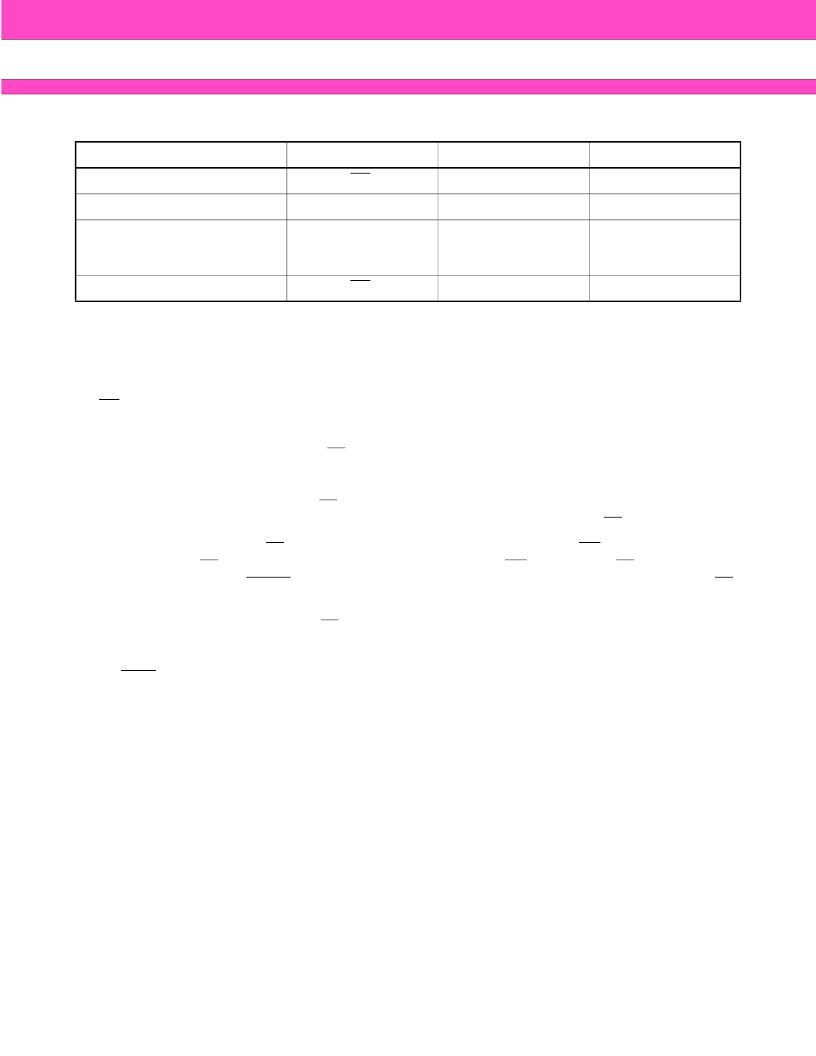
Notes:
1. Performing successive read operations from any address will cause DQ
6
to toggle.
2. Reading the byte address being programmed while in the erase-suspend program mode will indicate
logic “1” at the DQ
2
bit. However, successive reads from the erase-suspended sector will cause DQ
2
to
toggle.
RY/BY
Ready/Busy
The MBM29LV400TC/BC provide a RY/BY open-drain output pin as a way to indicate to the host system that
the Embedded Algorithms are either in progress or has been completed. If the output is low, the devices are
busy with either a program or erase operation. If the output is high, the devices are ready to accept any read/
write or erase operation. When the RY/BY pin is low, the devices will not accept any additional program or erase
commands. If the MBM29LV400TC/BC are placed in an Erase Suspend mode, the RY/BY output will be high.
During programming, the RY/BY pin is driven low after the rising edge of the fourth WE pulse. During an erase
operation, the RY/BY pin is driven low after the rising edge of the sixth WE pulse. The RY/BY pin will indicate a
busy condition during the RESET pulse. Refer to Figure 11 and 12 for a detailed timing diagram. The RY/BY
pin is pulled high in standby mode.
Since this is an open-drain output, RY/BY pins can be tied together in parallel with a pull-up resistor to V
CC
.
Byte/Word Configuration
The BYTE pin selects the byte (8-bit) mode or word (16-bit) mode for the MBM29LV400TC/BC devices. When
this pin is driven high, the devices operate in the word (16-bit) mode. The data is read and programmed at DQ
0
to DQ
15
. When this pin is driven low, the devices operate in byte (8-bit) mode. Under this mode, the DQ
15
/A
-1
pin
becomes the lowest address bit and DQ
8
to DQ
14
bits are tri-stated. However, the command bus cycle is always
an 8-bit operation and hence commands are written at DQ
0
to DQ
7
and the DQ
8
to DQ
15
bits are ignored. Refer
to Figures 13, 14 and 15 for the timing diagram.
Data Protection
The MBM29LV400TC/BC are designed to offer protection against accidental erasure or programming caused
by spurious system level signals that may exist during power transitions. During power up the devices
automatically reset the internal state machine in the Read mode. Also, with its control register architecture,
alteration of the memory contents only occurs after successful completion of specific multi-bus cycle command
sequences.
The devices also incorporate several features to prevent inadvertent write cycles resulting form V
CC
power-up
and power-down transitions or system noise.
Mode
DQ
7
DQ
6
DQ
2
Program
DQ
7
Toggle
1
Erase
0
Toggle
Toggle
Erase-Suspend Read
(Erase-Suspended Sector)
(Note 1)
1
1
Toggle
Erase-Suspend Program
DQ
7
Toggle (Note 1)
1 (Note 2)
相關(guān)PDF資料 |
PDF描述 |
|---|---|
| MBM29LV400TC-90PBT | 4M (512K X 8/256K X 16) BIT |
| MBM29LV400TC-90PF | 4M (512K X 8/256K X 16) BIT |
| MBM29LV400TC-90PFTN | 4M (512K X 8/256K X 16) BIT |
| MBM29LV400TC-90PFTR | 4M (512K X 8/256K X 16) BIT |
| MBM29LV400TC-70PFTR | 4M (512K X 8/256K X 16) BIT |
相關(guān)代理商/技術(shù)參數(shù) |
參數(shù)描述 |
|---|---|
| MBM29LV400TC-90PBT | 制造商:FUJITSU 制造商全稱:Fujitsu Component Limited. 功能描述:4M (512K X 8/256K X 16) BIT |
| MBM29LV400TC-90PBT-S-ER | 制造商:FUJITSU 功能描述: |
| MBM29LV400TC-90PCV | 制造商:FUJITSU 制造商全稱:Fujitsu Component Limited. 功能描述:4M (512K X 8/256K X 16) BIT |
| MBM29LV400TC-90PF | 制造商:SPANSION 制造商全稱:SPANSION 功能描述:FLASH MEMORY CMOS 4M (512K X 8/256K X 16) BIT |
| MBM29LV400TC-90PFTN | 制造商:FUJITSU 制造商全稱:Fujitsu Component Limited. 功能描述:4M (512K X 8/256K X 16) BIT |
發(fā)布緊急采購,3分鐘左右您將得到回復(fù)。