- 您現(xiàn)在的位置:買賣IC網(wǎng) > PDF目錄299470 > MBR10100CT (GENERAL SEMICONDUCTOR INC) 5 A, 100 V, SILICON, RECTIFIER DIODE, TO-220AB PDF資料下載
參數(shù)資料
| 型號: | MBR10100CT |
| 廠商: | GENERAL SEMICONDUCTOR INC |
| 元件分類: | 參考電壓二極管 |
| 英文描述: | 5 A, 100 V, SILICON, RECTIFIER DIODE, TO-220AB |
| 文件頁數(shù): | 1/2頁 |
| 文件大?。?/td> | 74K |
| 代理商: | MBR10100CT |
New
Product
Features
Plastic package has Underwriters Laboratory
Flammability Classification 94V-0
Dual rectifier construction, positive center tap
Metal silicon junction, majority carrier conduction
Low power loss, high efficiency
Guardring for overvoltage protection
For use in low voltage, high frequency inverters, free
wheeling, and polarity protection applications
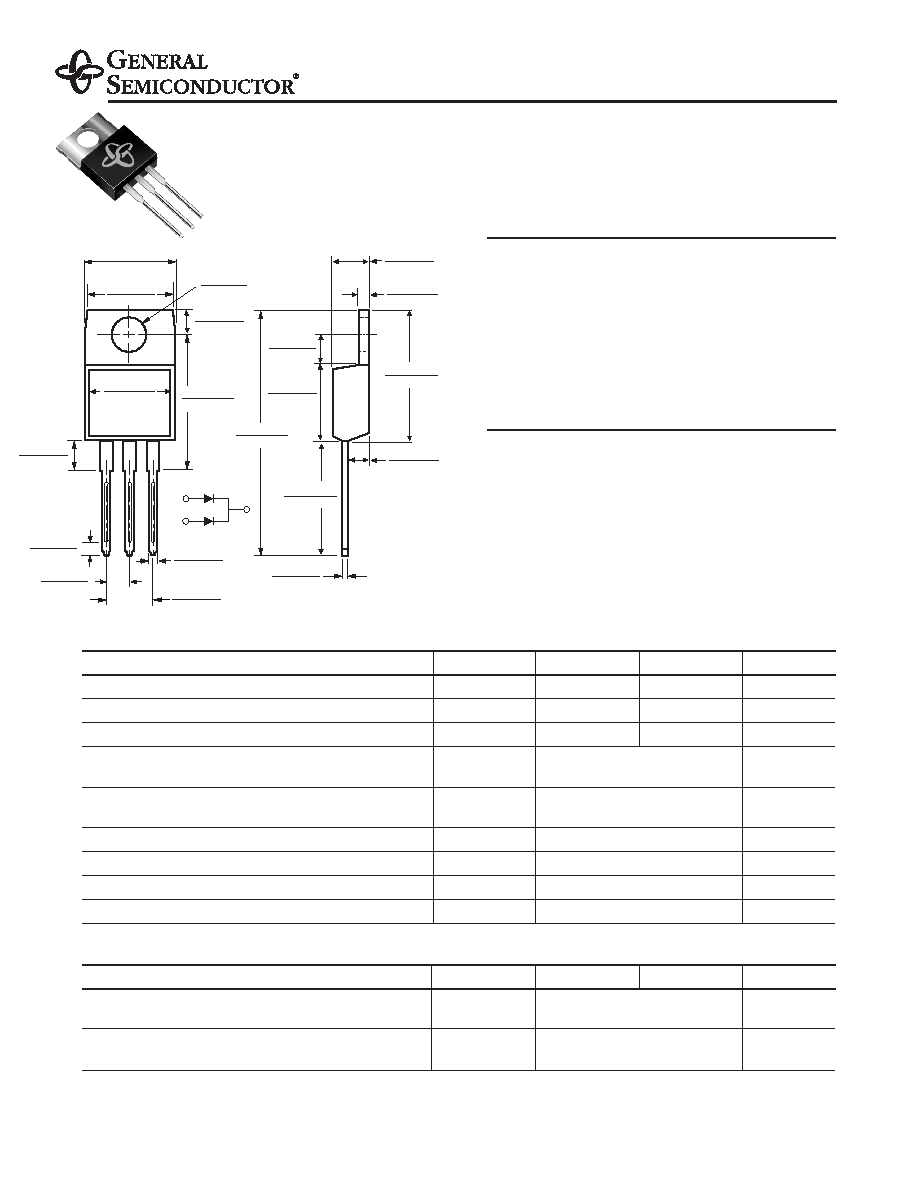
Mechanical Data
Case: JEDEC TO-220AB molded plastic body over
passivated chips
Terminals: Plated leads, solderable per
MIL-STD-750, Method 2026
High temperature soldering guaranteed:
250°C/10 seconds, 0.25" (6.35mm) from case
Polarity: As marked
Mounting Position: Any
Mounting Torque: 10 in-lbs maximum
Weight: 0.08oz., 2.24g
MBR1090CT thru MBR10100CT
Dual High-Voltage Schottky Rectifiers
Reverse Voltage 90 to 100V
Forward Current 10A
TO-220AB
12
3
PIN
0.185 (4.70)
0.175 (4.44)
0.055 (1.39)
0.045 (1.14)
0.145 (3.68)
0.135 (3.43)
0.350 (8.89)
0.330 (8.38)
0.560 (14.22)
0.530 (13.46)
0.022 (0.56)
0.014 (0.36)
0.110 (2.79)
0.100 (2.54)
0.603 (15.32)
0.573 (14.55)
CASE
1.148 (29.16)
1.118 (28.40)
PIN 2
0.154 (3.91)
0.148 (3.74)
0.113 (2.87)
0.103 (2.62)
0.160 (4.06)
0.140 (3.56)
0.410 (10.41)
0.390 (9.91)
0.635 (16.13)
0.625 (15.87)
0.415 (10.54) MAX.
0.370 (9.40)
0.360 (9.14)
PIN 1
PIN 3
0.028 (0.70)
0.104 (2.65)
0.096 (2.45)
0.035 (0.90)
0.205 (5.20)
0.195 (4.95)
0.105 (2.67)
0.095 (2.41)
Maximum Ratings and Thermal Characteristics (TC = 25°C unless otherwise noted)
Parameter
Symbol
MBR1090CT
MBR10100CT
Unit
Maximum repetitive peak reverse voltage
VRRM
90
100
V
Working peak reverse voltage
VRWM
90
100
V
Maximum DC blocking voltage
VDC
90
100
V
Maximum average forward rectified current Total device
10
at TC = 105°C
Per leg
IF(AV)
5
A
Peak forward surge current 8.3ms single half sine-wave
IFSM
120
A
superimposed on rated load (JEDEC Method) per leg
Peak repetitive reverse current per leg at tp = 2s, 1KHZ
IRRM
0.5
A
Voltage rate of change (rated VR)
dv/dt
10,000
V/s
Typical thermal resistance per leg
RθJC
4.4
°C/W
Operating junction and storage temperature range
TJ, TSTG
–65 to +150
°C
Electrical Characteristics (TC = 25°C unless otherwise noted)
Parameter
Symbol
MBR1090CT
MBR10100CT
Unit
Maximum instantaneous
at IF = 5.0A, TC = 125°C
VF
0.75
V
forward voltage per leg(4)
at IF = 5.0A, TC = 25°C
0.85
Maximum reverse current per leg
TJ = 25°C
100
A
at working peak reverse voltage(4)
TJ = 100°C
IR
6.0
mA
Notes: (1) Clip mounting (on case), where lead does not overlap heatsink with 0.110” offset
(2) Clip mounting (on case), where leads do overlap heatsink
(3) Screw mounting with 4-40 screw, where washer diameter is ≤ 4.9 mm (0.19”)
(4) Pulse test: 300s pulse width, 1% duty cycle
Dimensions in inches and (millimeters)
4/6/01
相關(guān)PDF資料 |
PDF描述 |
|---|---|
| MBR10150CTL | 10 A, 150 V, SILICON, RECTIFIER DIODE, TO-220AB |
| MBR12045 | 120 A, 45 V, SILICON, RECTIFIER DIODE |
| MBR150 | 1 A, 50 V, SILICON, SIGNAL DIODE, DO-41 |
| MBR1560CT | 15 A, 60 V, SILICON, RECTIFIER DIODE, TO-220AB |
| MBR20080 | 180 A, 80 V, SILICON, RECTIFIER DIODE |
相關(guān)代理商/技術(shù)參數(shù) |
參數(shù)描述 |
|---|---|
| MBR10100CT _T0 _10001 | 制造商:PanJit Touch Screens 功能描述: |
| MBR10100CT C0 | 制造商:SKMI/Taiwan 功能描述:Diode Schottky 100V 10A 3-Pin(3+Tab) TO-220AB Tube |
| MBR10100CT/45 | 功能描述:肖特基二極管與整流器 10 Amp 100 Volt RoHS:否 制造商:Skyworks Solutions, Inc. 產(chǎn)品:Schottky Diodes 峰值反向電壓:2 V 正向連續(xù)電流:50 mA 最大浪涌電流: 配置:Crossover Quad 恢復(fù)時間: 正向電壓下降:370 mV 最大反向漏泄電流: 最大功率耗散:75 mW 工作溫度范圍:- 65 C to + 150 C 安裝風(fēng)格:SMD/SMT 封裝 / 箱體:SOT-143 封裝:Reel |
| MBR10100CT_1 | 制造商:SIRECT 制造商全稱:Sirectifier Global Corp. 功能描述:Schottky Barrier Diode |
| MBR10100CT_12 | 制造商:SIRECT 制造商全稱:Sirectifier Global Corp. 功能描述:Power Schottky Rectifier - 10Amp 100Volt |
發(fā)布緊急采購,3分鐘左右您將得到回復(fù)。