- 您現(xiàn)在的位置:買賣IC網(wǎng) > PDF目錄383552 > MBR3035CT (Vishay Intertechnology,Inc.) Dual Schottky Rectifiers PDF資料下載
參數(shù)資料
| 型號: | MBR3035CT |
| 廠商: | Vishay Intertechnology,Inc. |
| 英文描述: | Dual Schottky Rectifiers |
| 中文描述: | 雙肖特基整流器 |
| 文件頁數(shù): | 1/3頁 |
| 文件大小: | 46K |
| 代理商: | MBR3035CT |
MBR3045CT, MBRF3045CT & MBRB3045CT Series
New Product
Vishay Semiconductors
formerly General Semiconductor
Dual Schottky Rectifiers
Reverse Voltage
30 to 45V
Forward Current
30A
0.08
(2.032)
0.24
(6.096)
0.42
(10.66)
0.63
(17.02)
0.12
(3.05)
0.33
(8.38)
Mounting Pad Layout TO-263AB
0.380 (9.65)
0.411 (10.45)
0.320 (8.13)
0.360 (9.14)
0.591 (15.00)
0.624 (15.85)
1
2
0.245 (6.22)
MIN
K
K
0.160 (4.06)
0.190 (4.83)
0.045 (1.14)
0.055 (1.40)
0.014 (0.36)
0.021 (0.53)
0.110 (2.79)
0.140 (3.56)
0.090 (2.29)
0.110 (2.79)
0.047 (1.19)
0.055 (1.40)
PIN 1
PIN 2
K - HEATSINK
0-0.01 (0-0.254)
0.027 (0.686)
0.037 (0.940)
0.105 (2.67)
0.095 (2.41)
0.205 (5.20)
0.195 (4.95)
1
3
PIN
2
0.060 (1.52)
0.405 (10.27)
0.383 (9.72)
0.191 (4.85)
0.171 (4.35)
0.600 (15.5)
0.580 (14.5)
0.560 (14.22)
0.530 (13.46)
0.037 (0.94)
0.027 (0.69)
0.140 (3.56)
0.130 (3.30)
0.350 (8.89)
0.330 (8.38)
0.188 (4.77)
0.172 (4.36)
0.110 (2.80)
0.100 (2.54)
0.131 (3.39)
0.122 (3.08)
0.110 (2.80)
0.100 (2.54)
0.022 (0.55)
0.014 (0.36)
DIA.
DIA.
0.676 (17.2)
0.646 (16.4)
0.205 (5.20)
0.195 (4.95)
0.105 (2.67)
0.095 (2.41)
PIN 2
PIN 1
PIN 3
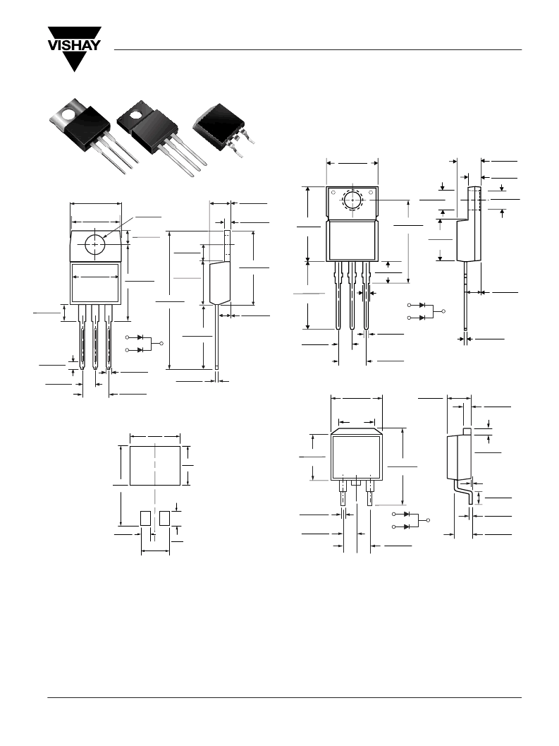
ITO-220AB (MBRF3035CT, MBRF3045CT)
TO-220AB (MBR3035CT, MBR3045CT)
Dimensions in inches
and (millimeters)
TO-263AB (MBRB3035CT, MBRB3045CT)
1
3
2
0.185 (4.70)
0.175 (4.44)
0.055 (1.39)
0.045 (1.14)
0.145 (3.68)
0.135 (3.43)
0.350 (8.89)
0.330 (8.38)
0.560 (14.22)
0.530 (13.46)
0.022 (0.56)
0.014 (0.36)
0.110 (2.79)
0.100 (2.54)
0.603 (15.32)
0.573 (14.55)
CASE
1.148 (29.16)
1.118 (28.40)
PIN 2
0.154 (3.91)
0.148 (3.74)
0.113 (2.87)
0.103 (2.62)
0.160 (4.06)
0.140 (3.56)
0.410 (10.41)
0.390 (9.91)
0.635 (16.13)
0.625 (15.87)
0.415 (10.54) MAX.
0.370 (9.40)
0.360 (9.14)
PIN 1
PIN 3
0.028 (0.70)
0.104 (2.65)
0.096 (2.45)
0.035 (0.90)
0.205 (5.20)
0.195 (4.95)
0.105 (2.67)
0.095 (2.41)
Features
Plastic package has Underwriters Laboratory
Flammability Classification 94V-0
Dual rectifier construction, positive center tap
Metal silicon junction, majority carrier conduction
Low power loss, high efficiency
Guardring for overvoltage protection
For use in low voltage, high frequency inverters, free
wheeling, and polarity protection applications
Mechanical Data
Case:
JEDEC TO-220AB, ITO-220AB, TO-263AB
molded plastic body
Terminals:
Plated leads, solderable per
MIL-STD-750, Method 2026
High temperature soldering guaranteed:
250°C/10 seconds, 0.25" (6.35mm) from case (TO-220AB,
ITO-220AB) at terminals (TO-236AB)
Polarity:
As marked
Mounting Position:
Any
Mounting Torque:
10 in-lbs maximum
Weight:
0.08 oz., 2.24 g
Document Number 88677
02-Oct-02
www.vishay.com
1
相關PDF資料 |
PDF描述 |
|---|---|
| MBR3045C | Dual Schottky Rectifiers |
| MBR3045CT | Dual Schottky Rectifiers |
| MBRB3035CT | Dual Schottky Rectifiers |
| MBRB3045CT | Dual Schottky Rectifiers |
| MBRF3035CT | Dual Schottky Rectifiers |
相關代理商/技術參數(shù) |
參數(shù)描述 |
|---|---|
| MBR3035CT_08 | 制造商:VISHAY 制造商全稱:Vishay Siliconix 功能描述:Schottky Rectifier, 2 x 15 A |
| MBR3035CT_1 | 制造商:TSC 制造商全稱:Taiwan Semiconductor Company, Ltd 功能描述:30.0 AMPS. Schottky Barrier Rectifiers |
| MBR3035CT_10 | 制造商:TSC 制造商全稱:Taiwan Semiconductor Company, Ltd 功能描述:30.0 AMPS. Schottky Barrier Rectifiers |
| MBR3035CT_11 | 制造商:TSC 制造商全稱:Taiwan Semiconductor Company, Ltd 功能描述:30.0AMPS. Schottky Barrier Rectifiers |
| MBR3035CT-1 | 制造商:VISHAY 制造商全稱:Vishay Siliconix 功能描述:Schottky Rectifier, 2 x 15 A |
發(fā)布緊急采購,3分鐘左右您將得到回復。