- 您現(xiàn)在的位置:買(mǎi)賣(mài)IC網(wǎng) > PDF目錄379309 > MC33215B (MOTOROLA INC) Telephone Line Interface and Speakerphone Circuit PDF資料下載
參數(shù)資料
| 型號(hào): | MC33215B |
| 廠商: | MOTOROLA INC |
| 元件分類: | 無(wú)繩電話/電話 |
| 英文描述: | Telephone Line Interface and Speakerphone Circuit |
| 中文描述: | TELEPHONE SPEECH CKT, PDIP42 |
| 封裝: | PLASTIC, SDIP-42 |
| 文件頁(yè)數(shù): | 11/20頁(yè) |
| 文件大小: | 456K |
| 代理商: | MC33215B |
第1頁(yè)第2頁(yè)第3頁(yè)第4頁(yè)第5頁(yè)第6頁(yè)第7頁(yè)第8頁(yè)第9頁(yè)第10頁(yè)當(dāng)前第11頁(yè)第12頁(yè)第13頁(yè)第14頁(yè)第15頁(yè)第16頁(yè)第17頁(yè)第18頁(yè)第19頁(yè)第20頁(yè)
MC33215
11
MOTOROLA ANALOG IC DEVICE DATA
RXI. A second high pass filtering is introduced by the
combination of C
GRX
and R
GRX
. A low pass filter is created
by C
RXO
and R
RXO
. The coupling capacitor at the output
RXO is not used for setting a high pass filter but merely for dc
decoupling.
In combination with dynamic ear capsules, the EAR
amplifier can become unstable due to the highly inductive
characteristic of some of the capsules. To regain stability, a
100 nF capacitor can be connected from RXS to Gnd in
those cases. An additional 10 nF at the RXI input, as shown
in the typical application, improves the noise figure of the
receiver stage.
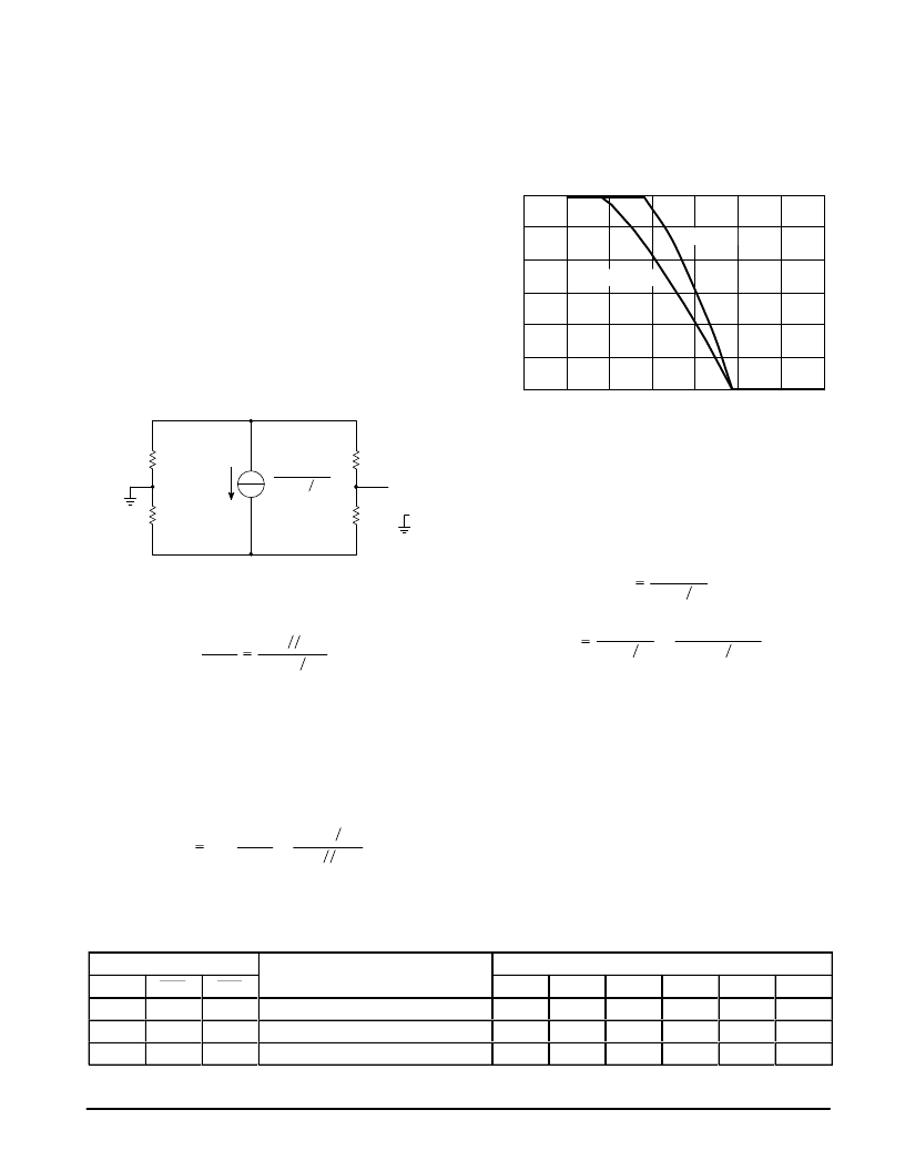
Sidetone Cancellation
The line driver and the receiver amplifier of the MC33215
are tied up in a bridge configuration as depicted in Figure 7.
This bridge configuration performs the so–called hybrid
function which, in the ideal case, prevents transmitted signals
from entering the receive channel.
Figure 7. Sidetone Bridge
VHMx 15
RSLP11
VLN
Z
line
//Z
set
SLP
R
SLP
/11
Gnd
Z
bal
R
SLB
Gnd
RXI
Receive
Transmit
As can be seen from Figure 7 by inspection, the receiver
will not pick up any transmit signal when the bridge is in
balance, that is to say when:
Zbal
RSLB
The sidetone suppression is normally measured in an
acoustic way. The signal at the earpiece when applying a
signal on the microphone is compared with the signal at the
earpiece when applying a signal on the line. The suppression
takes into account the transmit and receive gains set. In fact
the sidetone suppression can be given as a purely electrical
parameter given by the properties of the sidetone bridge
itself. For the MC33215, this so–called electrical sidetone
suppression A
STE
can be given as:
Zbal
RSLB
Values of –12 dB or better, thus A
STE
< 0.25, can easily be
reached in this way.
Zline
RSLP11
Zset
ASTE
1 –
x
RSLP11
Zline
Zset
Automatic Gain Control
To obtain more or less constant signal levels for transmit
and receive regardless of the telephone line length, both the
transmit and receive gain can be varied as a function of line
current when the AGC feature is used. The gain reduction as
a function of line current, and thus line length, is depicted in
Figure 8.
Figure 8. Automatic Gain Control
0
0
A
I
line
(mA)
–1.0
–2.0
–3.0
–4.0
–5.0
–6.0
10
20
30
40
50
60
70
R
AGC
= 20 k
R
AGC
= 30 k
For small line currents, and thus long lines, no gain
reduction is applied and thus the transmit and receive gains
are at their maximum. For line currents higher than I
start
, the
gain is gradually reduced until a line current I
stop
is reached.
This should be the equivalent of a very short line, and the
gain reduction equals 6.0 dB. For higher line currents the
gain is not reduced further. For the start and stop currents the
following relations are valid:
Istop
1
RSLP11
Istart
1
RSLP11
–
20
μ
x RAGC
RSLP11
For the typical application, where R
AGC
= 30 k
, the gain
will start to be reduced at I
start
= 20 mA while reaching 6.0 dB
of gain reduction at I
stop
= 50 mA. When AGC is connected to
V
DD
, the AGC function is disabled leading to no gain
reduction for any line current. This is also sometimes called
PABX mode.
The automatic gain control takes effect in the HMIC and R
x
amplifiers as well as in the BMIC amplifier. In this way the
AGC is also active in speakerphone mode, see the handsfree
operation paragraph.
Privacy and DTMF Mode
During handset operation a privacy and a DTMF mode can
be entered according the logic Table 1.
Table 1. Logic Table for Handset Mode
Logic Inputs
M d
Mode
Amplifiers
SPS
MUT
PRS
HMIC
BMIC
DTMF
R
x
RX
att
EAR
ááááááááááááááááááááááááááááááááá
ááááááááááááááááááááááááááááááááá
ááááááááááááááááááááááááááááááááá
0
1
1
Handset Normal
On
Off
Off
On
Off
On
0
1
0
Handset Privacy
Off
Off
On
On
Off
On
ááááááááááááááááááááááááááááááááá
0
0
X
Handset DTMF
Off
Off
On
Off
Off
On
相關(guān)PDF資料 |
PDF描述 |
|---|---|
| MC33215FB | Telephone Line Interface and Speakerphone Circuit |
| MC33219ADW | VOICE SWITCHED SPEAKERPHONE CIRCUIT |
| MC33219AP | VOICE SWITCHED SPEAKERPHONE CIRCUIT |
| MC33290D | ISO SERIAL LINK INTERFACE |
| MC33290 | ISO SERIAL LINK INTERFACE |
相關(guān)代理商/技術(shù)參數(shù) |
參數(shù)描述 |
|---|---|
| MC33215BE | 功能描述:電信語(yǔ)音調(diào)制 IC SPEAKERPHONE RoHS:否 制造商:Epson Electronics America 產(chǎn)品: 應(yīng)用:Voice Guidance product 封裝 / 箱體:PQFP-52 電源電壓-最大:3.6 V, 5.5 V 最大工作溫度: 最小工作溫度: 封裝: |
| MC33218AP | 制造商:Rochester Electronics LLC 功能描述: 制造商:Motorola Inc 功能描述: 制造商:MOTOROLA 功能描述: |
| MC33232D | 功能描述:功率因數(shù)校正 IC Critical Mode PFC RoHS:否 制造商:Fairchild Semiconductor 開(kāi)關(guān)頻率:300 KHz 最大功率耗散: 最大工作溫度:+ 125 C 安裝風(fēng)格:SMD/SMT 封裝 / 箱體:SOIC-8 封裝:Reel |
| MC33232DG | 功能描述:功率因數(shù)校正 IC Critical Mode PFC RoHS:否 制造商:Fairchild Semiconductor 開(kāi)關(guān)頻率:300 KHz 最大功率耗散: 最大工作溫度:+ 125 C 安裝風(fēng)格:SMD/SMT 封裝 / 箱體:SOIC-8 封裝:Reel |
| MC33232DR2 | 功能描述:功率因數(shù)校正 IC Critical Mode PFC RoHS:否 制造商:Fairchild Semiconductor 開(kāi)關(guān)頻率:300 KHz 最大功率耗散: 最大工作溫度:+ 125 C 安裝風(fēng)格:SMD/SMT 封裝 / 箱體:SOIC-8 封裝:Reel |
發(fā)布緊急采購(gòu),3分鐘左右您將得到回復(fù)。