- 您現(xiàn)在的位置:買賣IC網(wǎng) > PDF目錄371029 > MC33348D-4 (MOTOROLA INC) LITHIUM BATTERY PROTECTION CIRCUIT FOR ONE CELL SMART BATTERY PACKS PDF資料下載
參數(shù)資料
| 型號: | MC33348D-4 |
| 廠商: | MOTOROLA INC |
| 元件分類: | 電源管理 |
| 英文描述: | LITHIUM BATTERY PROTECTION CIRCUIT FOR ONE CELL SMART BATTERY PACKS |
| 中文描述: | 1-CHANNEL POWER SUPPLY SUPPORT CKT, PDSO8 |
| 封裝: | PLASTIC, SO-8 |
| 文件頁數(shù): | 7/12頁 |
| 文件大?。?/td> | 184K |
| 代理商: | MC33348D-4 |

MC33348
7
MOTOROLA ANALOG IC DEVICE DATA
INTRODUCTION
The insatiable demand for smaller lightweight portable
electronic equipment has dramatically increased the
requirements of battery performance. Batteries are expected
to have higher energy densities, superior cycle life, be safe in
operation and environmentally friendly. To address these
high expectations, battery manufacturers have invested
heavily in developing rechargeable lithium–based cells.
Today’s most attractive chemistries include lithium–polymer,
lithium–ion, and lithium–metal. Each of these chemistries
require electronic protection in order to constrain cell
operation to within the manufacturers limits.
Rechargeable lithium–based cells require precise charge
and discharge termination limits for both voltage and current
in order to maximize cell capacity, cycle life, and to protect
the end user from a catastrophic event. The termination limits
are not as well defined as with older non–lithium chemistries.
These limits are dependent upon a manufacturer’s particular
lithium chemistry, construction technique, and intended
application. Battery pack assemblers may also choose to
enhance cell capacity at the expense of cycle life. In order to
address these requirements, six versions of the MC33348
protection circuit were developed. These devices feature
charge overvoltage protection, discharge current limit
protection with delayed shutdown, low operating current, a
virtually zero current sleepmode state, and requires few
external components to implement a complete one cell smart
battery pack.
Operating Description
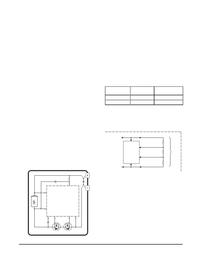
The MC33348 is specifically designed to be placed in the
battery pack where it is continuously powered from a single
lithium cell. In order to maintain cell operation within specified
limits, the protection circuit senses both cell voltage and
discharge current, and correspondingly controls the state of
two N–channel MOSFET switches. These switches, Q1 and
Q2, are placed in series with the negative terminal of the Cell
and the negative terminal of the battery pack. This
configuration allows the protection circuit to interrupt the
appropriate charge or discharge path FET in the event that
either a voltage threshold or the discharge current limit for the
cell has been exceeded.
8
4
6
5
1
3
MC33348
Cell
Charge
MOSFET Q1
Discharge
MOSFET Q2
7
Figure 8. One Cell Smart Battery Pack
A functional description of the protection circuit blocks
follows. Refer to the detailed block diagram shown in
Figure 7.
Voltage Sensing
Voltage sensing is accomplished by the use of the Cell
Voltage Sample Switch in conjunction with the Over/Under
Voltage Detector and Reference block. The Sample Switch
applies the cell voltage to the top resistor of an internal
divider string. The voltage at each of the tap points is
sequentially polled and compared to an internal reference. If
a limit has been exceeded, the result is stored in the
Over/Under Data Latch and Control Logic block. The Cell
Voltage Sample Switch is gated on for a 1.0 ms period at a
one second repetition rate. This low duty cycle sampling
technique reduces the average load current that the divider
presents across the cell, thus extending the useful battery
pack capacity. The cell voltage limits are tested in the
following sequence:
Figure 9. Cell Sensing Sequence
Polling
Sequence
Time
(ms)
Tested
Limit
ááááááááááááááá
ááááá
1
áááá
0.5
á
ááááá
á
Overvoltage
ááááááááááááááá
2
0.5
Undervoltage
By incorporating this polling technique with a single
comparator and voltage divider, a significant reduction of
circuitry and trim elements is achieved. This results in a
smaller die size, lower cost, and reduced operating current.
Figure 10. Cell Voltage Limit Sampling
From
Cell Voltage
Sample Switch
Over/Under
Cell Voltage
Detector
&
Reference
Discharge Voltage
Threshold
Charge Voltage
Threshold
Cell Voltage
Return
Cell Voltage
+
Cell
Voltage
–
R1
R2
R3
To
Cell Negative
Terminal
The cell charge and discharge voltage limits are controlled
by the values selected for the internal resistor divider string
and the comparator input threshold. As the battery pack
reaches full charge, the Cell Voltage Detector will sense an
overvoltage fault condition when the cell exceeds the
designed overvoltage limit. The fault information is stored in
a data latch and charge MOSFET Q1 is turned off,
disconnecting the battery pack from the charging source. An
internal current source pull–up is then applied to lower tap of
the divider, creating a hysteresis voltage. As a result of an
overvoltage fault, the battery pack is available for
discharging only.
The overvoltage fault is reset by applying a load to the
battery pack. As the voltage across the cell falls below the
hysteresis level, charge MOSFET Q1 will turn on and the
current source pull–up will turn off. The battery pack will now
be available for charging or discharging.
相關(guān)PDF資料 |
PDF描述 |
|---|---|
| MC33348D-5 | LITHIUM BATTERY PROTECTION CIRCUIT FOR ONE CELL SMART BATTERY PACKS |
| MC33348D-6 | LITHIUM BATTERY PROTECTION CIRCUIT FOR ONE CELL SMART BATTERY PACKS |
| MC3335 | Low Power Narrowband FM Receiver |
| MC3335DW | Low Power Narrowband FM Receiver |
| MC3335P | Low Power Narrowband FM Receiver |
相關(guān)代理商/技術(shù)參數(shù) |
參數(shù)描述 |
|---|---|
| MC33350SN-7T1 | 制造商:Rochester Electronics LLC 功能描述:- Bulk |
| MC33351ADTB-001 | 制造商:Rochester Electronics LLC 功能描述:- Bulk |
| MC33351DTB-001 | 制造商:ON Semiconductor 功能描述: |
| MC33362DW | 功能描述:直流/直流開關(guān)調(diào)節(jié)器 ANA HI VOLT OFFLN SW REG RoHS:否 制造商:International Rectifier 最大輸入電壓:21 V 開關(guān)頻率:1.5 MHz 輸出電壓:0.5 V to 0.86 V 輸出電流:4 A 輸出端數(shù)量: 最大工作溫度: 安裝風格:SMD/SMT 封裝 / 箱體:PQFN 4 x 5 |
| MC33362DWG | 功能描述:直流/直流開關(guān)調(diào)節(jié)器 ANA HI VOLT OFFLN SW REG RoHS:否 制造商:International Rectifier 最大輸入電壓:21 V 開關(guān)頻率:1.5 MHz 輸出電壓:0.5 V to 0.86 V 輸出電流:4 A 輸出端數(shù)量: 最大工作溫度: 安裝風格:SMD/SMT 封裝 / 箱體:PQFN 4 x 5 |
發(fā)布緊急采購,3分鐘左右您將得到回復(fù)。