- 您現(xiàn)在的位置:買賣IC網(wǎng) > PDF目錄369901 > MC44460 (Motorola, Inc.) PICTURE-IN-PICTURE (PIP) CONTROLLER PDF資料下載
參數(shù)資料
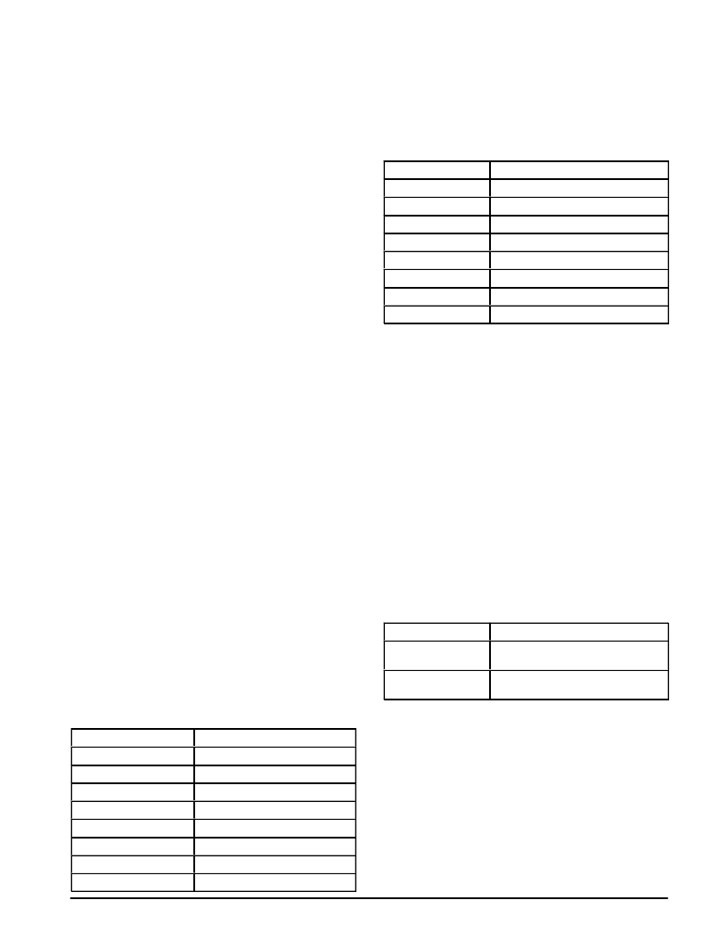
| 型號: | MC44460 |
| 廠商: | Motorola, Inc. |
| 英文描述: | PICTURE-IN-PICTURE (PIP) CONTROLLER |
| 中文描述: | 子母畫中畫(PIP)控制器 |
| 文件頁數(shù): | 10/16頁 |
| 文件大?。?/td> | 439K |
| 代理商: | MC44460 |
MC44460
10
MOTOROLA ANALOG IC DEVICE DATA
I2C REGISTER DESCRIPTIONS
Base read address = 24h
Base write address = 25h
Read Register
There are two active bits in the single read byte available
from the MC44460 as follows:
Write Vertical Indicator (WVI0) – D7
When 0 indicates that the write operation specified by the
last I2C command has been completed.
PIP Sync Detect Bit (PSD0) – D1
When 0 indicates that the PIP video H pulses are present
and the horizontal timebase oscillator is within acceptable
limits.
Write Registers
Read Start Position/Write Start Position Registers
Sub–address = 00h
Write Raster Position Start Bits (WPS0–2) – D0–D2
Establishes the horizontal beginning of the PIP and its
black level measurement gate. This beginning may be varied
by approximately 3.0
μ
s. The position of this pulse may be
observed through the Multi Test Pin 30 (See Test Mode
Register Sub–address 03h).
Read Raster Position Bits (RPS0–3) – D4–D7
Establishes the clamp gate position for the black level
reference for the main picture. This position may be varied by
approximately 5.0
μ
s. The position of this pulse may be
observed through the Multi Test Pin 30 (See Test Mode
Register Sub–address 03h).
Pip Switch Delay/Vertical Filter Register
Sub–address = 01h
PIP Switch Delay Bits (PSD0–3) – D0–D3
Delays the start of PIP on time relative to the PIP picture.
These bits are used to center the PIP border and PIP picture
in the horizontal direction.
Vertical Filter Bit (VFON) – D4
When the filter is activated (VFON = 1) a three line
weighted average is taken to provide the data stored in the
field memory.
Border Color Register
Sub–address = 02h
Border Color Bits (BC0–2) – D0–D2
These Bits control the color of the border. Note that when
using one of the saturated border colors it is possible to get
objectionable dot crawl at the edge of the border in some TVs
áááááááá
áááááááá
BC (2:0)
000
áááááááááá
áááááááááá
Border Color
Black
áááááááá
001
áááááááááá
White 70%
áááááááá
ááááááááááááááááá
010
áááááááááá
No Border (clear)
áááááááá
011
áááááááááá
No Border (clear)
100
Blue
áááááááá
101
áááááááááá
Green
áááááááá
110
áááááááááá
Red
áááááááá
ááááááááááááááááá
111
áááááááááá
White
áááááááá
áááááááá
áááááááááá
áááááááááá
Test Mode/Main Vertical and Horizontal Polarity Register
Sub–address = 03h
Internal Test Mode Register (ITM0–2) – D0–D2
Sets the Multi Test Pin output to provide one of several
internal signals for test and production alignment. Also
controls the test memory address counter.
áááááá
áááááá
áááááá
ITM (2:0)
000
Multi–Test I/O and Function
Input – Analog Test mode
áááááá
001
ááááááááááá
Input – Digital Test mode
áááááááááááááááá
ááááááááááá
áááááá
011
ááááááááááá
Output – Multi PIP Switch
áááááá
ááááááááááá
áááááá
áááááááááááááááá
ááááááááááá
áááááá
ááááááááááá
áááááá
ááááááááááá
áááááá
áááááá
Main vertical polarity select bit (MVP0) – D6
Selects polarity of active level of vertical reference input.
0 = positive going, 1 = negative going.
Main horizontal polarity select bit (MHP0) – D7
Selects polarity of active level of horizontal reference
input. 0 = positive going, 1 = negative going.
PIP Freeze/PIP Size/Main and PIP Video Source Register
Sub–address = 04h
PIP Freeze Bit (STIL0) – D4
When set to one, the most recently received field is
continuously displayed until the freeze bit is cleared.
PIP Size Bit (PSI90) – D5
Switches the PIP size between 1/16 main size (when 0)
and 1/9 main size (when 1).
Main Video Source Select Bit (MSEL0) – D6
Selects which video input will be applied to the PIP switch
as the main video out.
PIP Video Source Select Bit (PSEL0) – D7
Selects which video input will be applied to the video
decoder to provide the PIP video.
ááááááááááá
ááááááááááá
áááááá
áááááá
MSEL/PSEL
áááááá
0
áááááá
ááááááááááá
Function
ááááááááááá
Video 1 Input to Main/
áááááá
ááááááááááá
áááááá
áááááá
PIP On/PIP Blank Register
Sub–address = 05h
PIP On Bit (PON0) – D0
When on (1) turns the PIP on.
PIP Blanking Bit (PBL0) – D4
When on (1) sets the PIP to black. If the PIP is off, then it
will be black if it is turned on. Overrides all other settings of
the PIP control.
PIP X Position Register
Sub–address = 06h
X Position Bits (XPS0–5) – D0–D5
Moves the PIP start position from the left to the right
edge of the display in 64 steps. There is protection circuitry
ááááááááááá
ááááááááááá
相關(guān)PDF資料 |
PDF描述 |
|---|---|
| MC44461B | RV Series - Econoline Unregulated DC-DC Converters; Input Voltage (Vdc): 24V; Output Voltage (Vdc): 05V; Power: 2W; High Isolation 2W Converter; Approved for Medical Applications; EN and UL Safety Certificates; 6kVDC Isolation; Skinny DIP24 Package; Optional Continuous Short Circuit Protected; Fully Encapsulated; Very Low Isolation Capacitance |
| MC44461 | PICTURE-IN-PICTURE (PIP) CONTROLLER |
| MC44462B | Y-C PICTURE-IN-PICTURE (PIP) CONTROLLER |
| MC44462 | Y-C PICTURE-IN-PICTURE (PIP) CONTROLLER |
| MC44463B | RV Series - Econoline Unregulated DC-DC Converters; Input Voltage (Vdc): 24V; Output Voltage (Vdc): 09V; Power: 2W; High Isolation 2W Converter; Approved for Medical Applications; EN and UL Safety Certificates; 6kVDC Isolation; Skinny DIP24 Package; Optional Continuous Short Circuit Protected; Fully Encapsulated; Very Low Isolation Capacitance |
相關(guān)代理商/技術(shù)參數(shù) |
參數(shù)描述 |
|---|---|
| MC44460B | 制造商:MOTOROLA 制造商全稱:Motorola, Inc 功能描述:PICTURE-IN-PICTURE (PIP) CONTROLLER |
| MC44461 | 制造商:MOTOROLA 制造商全稱:Motorola, Inc 功能描述:PICTURE-IN-PICTURE (PIP) CONTROLLER |
| MC44461B | 制造商:MOTOROLA 制造商全稱:Motorola, Inc 功能描述:PICTURE-IN-PICTURE (PIP) CONTROLLER |
| MC44462 | 制造商:MOTOROLA 制造商全稱:Motorola, Inc 功能描述:Y-C PICTURE-IN-PICTURE (PIP) CONTROLLER |
| MC44462B | 制造商:MOTOROLA 制造商全稱:Motorola, Inc 功能描述:Y-C PICTURE-IN-PICTURE (PIP) CONTROLLER |
發(fā)布緊急采購,3分鐘左右您將得到回復(fù)。