- 您現(xiàn)在的位置:買賣IC網(wǎng) > PDF目錄369901 > MC44BC373DTB (MOTOROLA INC) Multi-Standard or PAL/ NTSC Modulator with integrated antenna booster/splitter ICs PDF資料下載
參數(shù)資料
| 型號: | MC44BC373DTB |
| 廠商: | MOTOROLA INC |
| 元件分類: | 消費家電 |
| 英文描述: | Multi-Standard or PAL/ NTSC Modulator with integrated antenna booster/splitter ICs |
| 中文描述: | SPECIALTY CONSUMER CIRCUIT, PDSO24 |
| 封裝: | TSSOP-24 |
| 文件頁數(shù): | 16/24頁 |
| 文件大?。?/td> | 635K |
| 代理商: | MC44BC373DTB |
16
MC44BC373/374 Technical Data
For More Information On This Product,
Go to: www.freescale.com
MOTOROLA
Modulator Operation
There is a time-out of 263ms until the output is enabled. This allows the UHF PLL settle to its
programmed frequency. During the 263ms time-out, the sound PLL current source is set to 10
μ
A typical,
to speed up the locking time. After the 263ms time-out, the current source is switched to 1
μ
A.
CAUTION:
Use care when selecting loop filter components, to ensure the loop
transient does not exceed the specified delay.
For test purposes, it is possible to disable the 263ms delay using Test Mode1–State1
.
h.
12.7 Logic Output Port (LOP)
The LOP pin controls any logic function. The primary applications are to control an external attenuator or
an external switch between the antenna input and TV output. When an external switch is controlled, the
Booster function is not used.
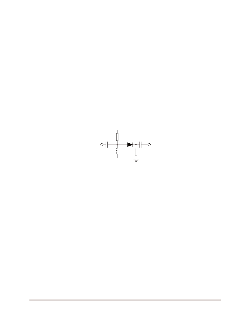
The following figure shows a typical attenuator application with PIN diode. The LOP pin switches the
PIN attenuator depending on the signal strength of the Antenna Input, thereby reducing the risks of
Intermodulation in certain areas. The LOP may also be used as an OFF position bypass switch or for other
logic functions in the application.
Figure 9. Attenuator Application with PIN Diode
12.8 Video Section—Peak White Clip
The modulator requires the following:
A composite video input with “negative going” sync pulses
A nominal level of 1Vp-p
This signal is AC-coupled to the video input where the sync tip level is clamped. The video signal is then
passed to a Peak White Clip (PWC) circuit. The PWC circuit function sets to soft-clip the top of the video
waveform, if the “sync tip amplitude” to “peak white clip” goes too high. This method avoids carrier over-
modulation by the video. Clipping can be disabled by software.
12.9 Sound Section
The multivibrator oscillator is fully integrated and does not require external components. An internal low
pass filter and matched structure provide a very low harmonics level.
The sound modulator system consists of an FM modulator incorporating the sound subcarrier oscillator,
and an AM modulator. The audio input signal is AC coupled into the amplifier which then drives the two
types of modulators.
The audio pre-emphasis circuit is a high-pass filter with an external capacitor and an internal resistor
(100kOhms). The recommended capacitor value (470pF) is for BG standard. (50
μ
S time constant.)
LOP pin
Vcc
TV Out
Antenna
Input
F
Freescale Semiconductor, Inc.
n
.
相關(guān)PDF資料 |
PDF描述 |
|---|---|
| MC44BC374 | Multi-Standard or PAL/ NTSC Modulator with integrated antenna booster/splitter ICs |
| MC44BC374DTB | Multi-Standard or PAL/ NTSC Modulator with integrated antenna booster/splitter ICs |
| MC44BC374T1D | PLL Tuned PAL/NTSC UHF and VHF Audio/ Video High Integration Modulator IC |
| MC44BC374CDTB | PLL Tuned UHF and VHF Audio/Video High Integration Modulator |
| MC44BC374C | PLL Tuned UHF and VHF Audio/Video High Integration Modulator |
相關(guān)代理商/技術(shù)參數(shù) |
參數(shù)描述 |
|---|---|
| MC44BC373DTBR2 | 制造商:Freescale Semiconductor 功能描述: |
| MC44BC373EJB | 制造商:Freescale Semiconductor 功能描述:BCMOS MODULATOR MULTI STD |
| MC44BC374 | 制造商:MOTOROLA 制造商全稱:Motorola, Inc 功能描述:PLL Tuned PAL/NTSC UHF and VHF Audio/ Video High Integration Modulator IC |
| MC44BC374C | 制造商:MOTOROLA 制造商全稱:Motorola, Inc 功能描述:PLL Tuned UHF and VHF Audio/Video High Integration Modulator |
| MC44BC374CD | 制造商:MOTOROLA 制造商全稱:Motorola, Inc 功能描述:PLL Tuned UHF and VHF Audio/Video High Integration Modulator |
發(fā)布緊急采購,3分鐘左右您將得到回復(fù)。