- 您現(xiàn)在的位置:買賣IC網(wǎng) > PDF目錄369901 > MC44BC374CD (MOTOROLA INC) PLL Tuned UHF and VHF Audio/Video High Integration Modulator PDF資料下載
參數(shù)資料
| 型號: | MC44BC374CD |
| 廠商: | MOTOROLA INC |
| 元件分類: | 消費家電 |
| 英文描述: | PLL Tuned UHF and VHF Audio/Video High Integration Modulator |
| 中文描述: | SPECIALTY CONSUMER CIRCUIT, PDSO16 |
| 封裝: | SO-16 |
| 文件頁數(shù): | 18/30頁 |
| 文件大小: | 915K |
| 代理商: | MC44BC374CD |
第1頁第2頁第3頁第4頁第5頁第6頁第7頁第8頁第9頁第10頁第11頁第12頁第13頁第14頁第15頁第16頁第17頁當前第18頁第19頁第20頁第21頁第22頁第23頁第24頁第25頁第26頁第27頁第28頁第29頁第30頁
18
MC44BC373C/374C Technical Data
For More Information On This Product,
Go to: www.freescale.com
MOTOROLA
Modulator Description
13.5
Test Bit TB1
This test bit allows a different bus format.
TB1=0 — All MC44BC373C/4C Functions Available—Normal Mode.
TB1=1 — Limited Software Compatibility with MC443533. MC44BC373C/4C Functions Not
Available. TB1=1, allows a first evaluation of MC44BC373C/4C using software developed for
MC44353 devices.
13.6
Transient Output Inhibit
To minimize the risk of interference to other channels while the UHF PLL is acquiring a lock on the
desired frequency, the Sound and Video modulators are turned OFF during a time out period for each of
the following two cases:
Power-ON from zero (i.e., all Vcc is switched from 0V to 5V).
UHF oscillator power-ON from OFF state (i.e., OSC bit is switched from 1 to 0)
There is a time-out of 263ms until the output is enabled. This lets the UHF PLL settle to its programmed
frequency. During the 263ms time-out, the sound PLL current source is set to 10
μ
A typical to speed up the
locking time. After the 263ms time-out, the current source is switched to 1
μ
A. Use care when selecting
loop filter components, to ensure the loop transient does not exceed this delay.
For test purposes, it is possible to disable the 263ms delay using Test Mode1–State1.h (this is called speed
up mode).
13.7
UHF Oscillator—VHF range
The UHF oscillator is fully integrated and does not require any external components.
For low frequency testing or VHF range operation (test mode 1, states 1.b to 1.c), the UHF oscillator can
be internally divided by: 2, 4, 8, or 16.
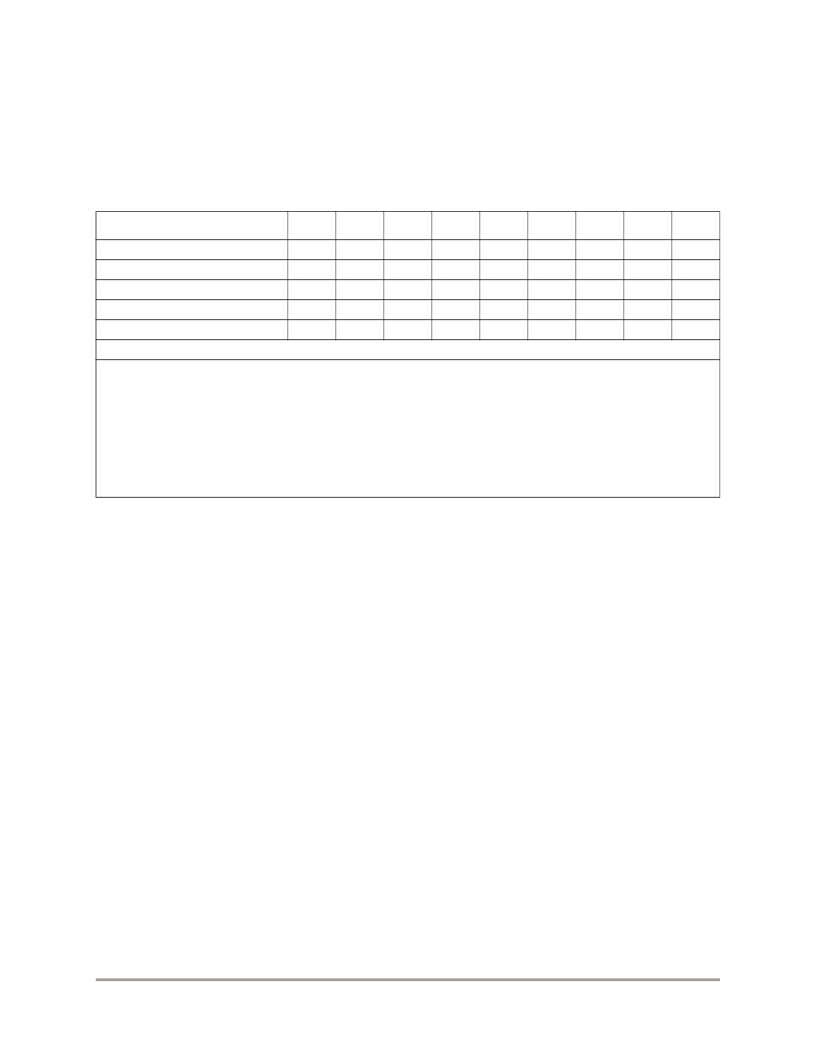
WRITE MODE
Bit 7
Bit 6
Bit 5
Bit 4
Bit 3
Bit 2
Bit 1
Bit 0
ACK
CA
—
CHIP ADDRESS
1
1
0
0
1
0
1
0
ACK
C1
—
High Order Bits
1
*
*
*
PS
*
*
SYSL
ACK
C0
—
Low Order Bits
*
*
*
SFD1
SFD0
1
0
0
ACK
FM
—
High Order Bits
0
TPEN
N11
N10
N9
N8
N7
N6
ACK
FL
—
Low Order Bits
N5
N4
N3
N2
N1
N0
*
*
ACK
Case TB1=1 compatible with MC44353
All
“
”
are don
’
t care bits.
PS bit replaces PSD2 bit in MC44353 bus format:
PS = 0 is for Picture-to-Sound ratio = 12dB
PS = 1 is for Picture-to-Sound ratio = 16dB
SFD1 and SFD0 bits have the same definition for both bus formats (MC44353 and MC44BC373C/4C) and
allows a select sound frequency between 4.5MHz, 5MHz, 5.5MHz, and 6.5MHz.
SYSL bit is the same definition for both bus formats (MC44353 and MC44BC373C/4C) and allows a select
system L or BG.
All MC44BC373C/4C functions are set to their default values.
F
Freescale Semiconductor, Inc.
n
.
相關PDF資料 |
PDF描述 |
|---|---|
| MC54F02J | QUAD 2-INPUT NOR GATE FAST SCHOTTKY TTL |
| MC54F02 | QUAD 2-INPUT NOR GATE FAST SCHOTTKY TTL |
| MC74F02N | QUAD 2-INPUT NOR GATE FAST SCHOTTKY TTL |
| MC74F02D | QUAD 2-INPUT NOR GATE FAST SCHOTTKY TTL |
| MC68008 | 16-Bit Microprocessor(16位微處理器) |
相關代理商/技術參數(shù) |
參數(shù)描述 |
|---|---|
| MC44BC374CDR2 | 制造商:FREESCALE 制造商全稱:Freescale Semiconductor, Inc 功能描述:PLL Tuned UHF and VHF Audio/Video High Integration Modulator |
| MC44BC374CDTB | 制造商:Rochester Electronics LLC 功能描述:- Bulk |
| MC44BC374CDTBR2 | 制造商:Rochester Electronics LLC 功能描述:- Bulk |
| MC44BC374CED | 制造商:Motorola Inc 功能描述: |
| MC44BC374CEDR2 | 制造商:Rochester Electronics LLC 功能描述:- Bulk 制造商:Motorola Inc 功能描述: 制造商:MOTOROLA 功能描述: |
發(fā)布緊急采購,3分鐘左右您將得到回復。