- 您現(xiàn)在的位置:買賣IC網(wǎng) > PDF目錄371042 > MC68160CFB (MOTOROLA INC) 3.0V 100ppm/Degrees C, 50uA in SOT23-3 Series (Bandgap) Voltage Reference 3-SOT-23 -40 to 125 PDF資料下載
參數(shù)資料
| 型號: | MC68160CFB |
| 廠商: | MOTOROLA INC |
| 元件分類: | 網(wǎng)絡接口 |
| 英文描述: | 3.0V 100ppm/Degrees C, 50uA in SOT23-3 Series (Bandgap) Voltage Reference 3-SOT-23 -40 to 125 |
| 中文描述: | DATACOM, ETHERNET TRANSCEIVER, PQFP52 |
| 封裝: | PLASTIC, TQFP-52 |
| 文件頁數(shù): | 27/30頁 |
| 文件大小: | 372K |
| 代理商: | MC68160CFB |
第1頁第2頁第3頁第4頁第5頁第6頁第7頁第8頁第9頁第10頁第11頁第12頁第13頁第14頁第15頁第16頁第17頁第18頁第19頁第20頁第21頁第22頁第23頁第24頁第25頁第26頁當前第27頁第28頁第29頁第30頁

MC68160 MC68160B MC68160C
APPLICATIONS INFORMATION
27
MOTOROLA ANALOG IC DEVICE DATA
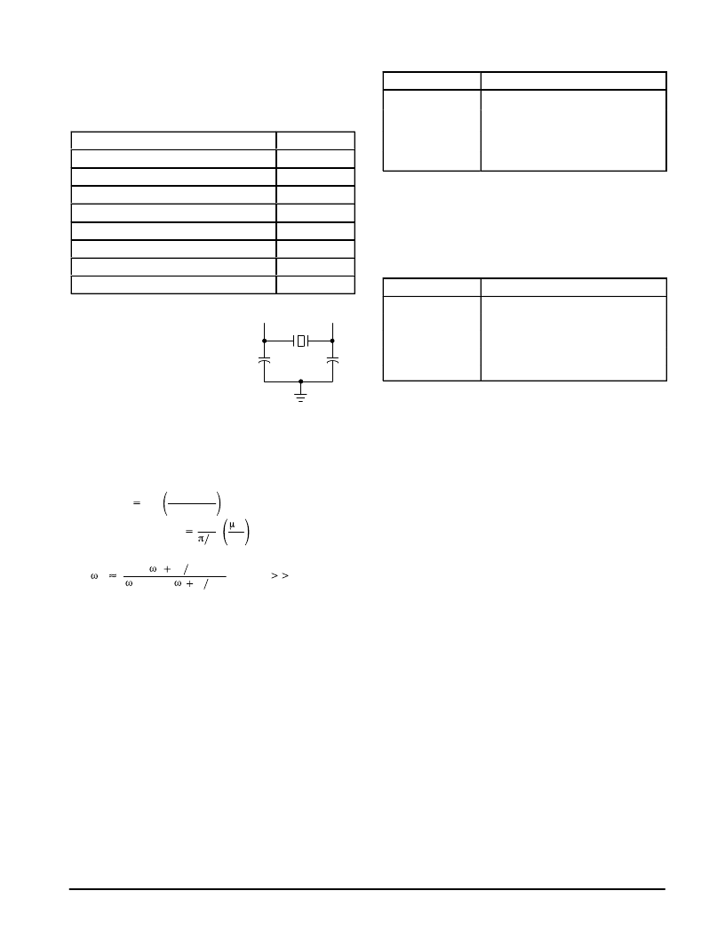
Selection of Crystal and External Components
Accuracy of frequency and stability over temperature are
the main determinants of crystal choice. Specifications for a
suitable crystal are tabulated below.
áááááááááááááááá
áááááááááááááááá
áááááááááááááááá
áááááááááááááááá
áááááááááááááááá
áááááááááááááááá
áááááááááááááááá
Mode
Fundamental
áááááááááááááááá
Tolerance
±
100 ppm
Stability
100 ppm
Aging
áááááááááááááááá
Shunt Capacitance
Load Capacitance
áááááááááááááááá
Series Fundamental Resistance (ESR)
Drive Level
7.0 pF
18–20 pF
25
500
μ
W
X1
X2
1
2
C5
C4
A suitable crystal is the MTRON
HC49 MP–1, 20.000 MHz crystal.
20 pF for C4 and C5 have been
shown to work reliably.
PLL Filter Components
The filter components at Pin 12 were chosen to assure
adequate pull–range but with a emphasis on stability. It is not
foreseeable that a design would need to change the
components, but for the sake of completeness, relevant
values are provided here.
MHz
Volt
sec
100
2
filter impedance function is;
(j
1 C6)
j
C5
(j
1 C5)
VCO Gain
24
and,
Phase Detector Gain
A
rad
and the
Z(j )
(for C6
C5)
10BASE–T Filter and Transformer Choice
The MC68160, B and C differential outputs are low
impedance voltage sources. Therefore, external series
resistors must be used in order to match the characteristic
impedance of twisted pair. Since the output resistance of
each leg of the transmitter is about 10
, a 39
resistor is
used in series as shown in the applications schematic. So the
impedance presented from the source to the isolation
transformer is then very nearly 100
. The following is a list of
some 10BASE–T filter module vendors and their products.
Vendor
FEE Fil–Mag
Valor Electronics
Pulse Engineering
TOKO
Part #
78Z1120B–01, 78Z1122B/D–01,
78Z1122 F–01
PT3877, FL1012, FL1066
PE–65434, PE65424, PE65433
PM01–00, PM02–00, PM05–00
AUI Transformer Choice
Like the 10BASE–T outputs, the AUI differential outputs
are low impedance sources and capable of meeting the IEEE
802.3 waveform requirements when a coupling transformer
is used. Some AUI transformer vendors and their products
are provided below.
Vendor
Coilcraft
FEE Fil–Mag
Valor Electronics
Pulse Engineering
TOKO
Part #
LAX–ET304
23Z90, 23Z91/ 23Z92
LT6032, LT6033
PE64502, PE6103
Q30ALQ8 1AA3 Q30ALQ9 1AA3
Q30ALQ8–1AA3, Q30ALQ9–1AA3
Application Notes:
The following procedure is applicable to all three versions
MC68160, MC68160B and MC68160C. References to the
MC68160 includes all the versions.
Resetting the MC68160 after power up.
In some applications, after initial power up, the MC68160
may not be able to transmit or receive data. This is usually
caused by the LOOP and TPFULDL control lines being active
at the same time. This is an illegal condition during normal
operation, it places the MC68160 into the production test
mode.
To exit the test mode and return to normal: Set LOOP low,
TPFULDL high and TPSQEL low. Then, while keeping
TPSQEL low, raise LOOP after 300 ms lower TPFULDL. This
will put the MC68160 into test mode but also resets the
MC68160. After 500 ms lower LOOP to get out of the test
mode. TPFULDL may then be de–asserted if desired.
The MC68160 is now ready for operation.
A hardware implementation of this fix would be to place a
pull down resistor on the TPSQEL pin. Even if test mode is
entered by accident, this ensures that zero’s will be written to
the test register. The hardware implementation will solve the
problem if the test mode is entered because of noise on the
TPSQEL pin. If the controller is toggling the MC68160 lines
while it is booting up, the reset procedure must be followed.
相關PDF資料 |
PDF描述 |
|---|---|
| MC68160FB | ENHANCED ETHERNET INTERFACE TRANSCEIVER |
| MC68175 | FLEXchip Decoder(FLEXchip譯碼器) |
| MC68176 | 2-bit A/D Converter(2位A/D轉(zhuǎn)換器) |
| MC68177 | FLEXchip Decoder(FLEXchip譯碼器) |
| MC68181 | Roaming FLEXchip(漫游式FLEX芯片) |
相關代理商/技術(shù)參數(shù) |
參數(shù)描述 |
|---|---|
| MC68160FB | 制造商:Freescale Semiconductor 功能描述: 制造商:Motorola Inc 功能描述: 制造商: 功能描述: 制造商:undefined 功能描述: |
| MC68181 | 制造商:FREESCALE 制造商全稱:Freescale Semiconductor, Inc 功能描述:Advance Information ROAMING FLEX chip SIGNAL PROCESSOR |
| MC68184 | 制造商:MOTOROLA 制造商全稱:Motorola, Inc 功能描述:Broadband Interface Controller |
| MC68185 | 制造商:MOTOROLA 制造商全稱:Motorola, Inc 功能描述:MC68185 Twisted-Pair Modem(TPM) |
| MC68194 | 制造商:ONSEMI 制造商全稱:ON Semiconductor 功能描述:Carrier Band Modem(CBM) |
發(fā)布緊急采購,3分鐘左右您將得到回復。