- 您現(xiàn)在的位置:買賣IC網(wǎng) > PDF目錄359146 > MC68HC908GR8 (Motorola, Inc.) Microcontrollers PDF資料下載
參數(shù)資料
| 型號(hào): | MC68HC908GR8 |
| 廠商: | Motorola, Inc. |
| 英文描述: | Microcontrollers |
| 中文描述: | 微控制器 |
| 文件頁(yè)數(shù): | 4/278頁(yè) |
| 文件大?。?/td> | 4699K |
| 代理商: | MC68HC908GR8 |
第1頁(yè)第2頁(yè)第3頁(yè)當(dāng)前第4頁(yè)第5頁(yè)第6頁(yè)第7頁(yè)第8頁(yè)第9頁(yè)第10頁(yè)第11頁(yè)第12頁(yè)第13頁(yè)第14頁(yè)第15頁(yè)第16頁(yè)第17頁(yè)第18頁(yè)第19頁(yè)第20頁(yè)第21頁(yè)第22頁(yè)第23頁(yè)第24頁(yè)第25頁(yè)第26頁(yè)第27頁(yè)第28頁(yè)第29頁(yè)第30頁(yè)第31頁(yè)第32頁(yè)第33頁(yè)第34頁(yè)第35頁(yè)第36頁(yè)第37頁(yè)第38頁(yè)第39頁(yè)第40頁(yè)第41頁(yè)第42頁(yè)第43頁(yè)第44頁(yè)第45頁(yè)第46頁(yè)第47頁(yè)第48頁(yè)第49頁(yè)第50頁(yè)第51頁(yè)第52頁(yè)第53頁(yè)第54頁(yè)第55頁(yè)第56頁(yè)第57頁(yè)第58頁(yè)第59頁(yè)第60頁(yè)第61頁(yè)第62頁(yè)第63頁(yè)第64頁(yè)第65頁(yè)第66頁(yè)第67頁(yè)第68頁(yè)第69頁(yè)第70頁(yè)第71頁(yè)第72頁(yè)第73頁(yè)第74頁(yè)第75頁(yè)第76頁(yè)第77頁(yè)第78頁(yè)第79頁(yè)第80頁(yè)第81頁(yè)第82頁(yè)第83頁(yè)第84頁(yè)第85頁(yè)第86頁(yè)第87頁(yè)第88頁(yè)第89頁(yè)第90頁(yè)第91頁(yè)第92頁(yè)第93頁(yè)第94頁(yè)第95頁(yè)第96頁(yè)第97頁(yè)第98頁(yè)第99頁(yè)第100頁(yè)第101頁(yè)第102頁(yè)第103頁(yè)第104頁(yè)第105頁(yè)第106頁(yè)第107頁(yè)第108頁(yè)第109頁(yè)第110頁(yè)第111頁(yè)第112頁(yè)第113頁(yè)第114頁(yè)第115頁(yè)第116頁(yè)第117頁(yè)第118頁(yè)第119頁(yè)第120頁(yè)第121頁(yè)第122頁(yè)第123頁(yè)第124頁(yè)第125頁(yè)第126頁(yè)第127頁(yè)第128頁(yè)第129頁(yè)第130頁(yè)第131頁(yè)第132頁(yè)第133頁(yè)第134頁(yè)第135頁(yè)第136頁(yè)第137頁(yè)第138頁(yè)第139頁(yè)第140頁(yè)第141頁(yè)第142頁(yè)第143頁(yè)第144頁(yè)第145頁(yè)第146頁(yè)第147頁(yè)第148頁(yè)第149頁(yè)第150頁(yè)第151頁(yè)第152頁(yè)第153頁(yè)第154頁(yè)第155頁(yè)第156頁(yè)第157頁(yè)第158頁(yè)第159頁(yè)第160頁(yè)第161頁(yè)第162頁(yè)第163頁(yè)第164頁(yè)第165頁(yè)第166頁(yè)第167頁(yè)第168頁(yè)第169頁(yè)第170頁(yè)第171頁(yè)第172頁(yè)第173頁(yè)第174頁(yè)第175頁(yè)第176頁(yè)第177頁(yè)第178頁(yè)第179頁(yè)第180頁(yè)第181頁(yè)第182頁(yè)第183頁(yè)第184頁(yè)第185頁(yè)第186頁(yè)第187頁(yè)第188頁(yè)第189頁(yè)第190頁(yè)第191頁(yè)第192頁(yè)第193頁(yè)第194頁(yè)第195頁(yè)第196頁(yè)第197頁(yè)第198頁(yè)第199頁(yè)第200頁(yè)第201頁(yè)第202頁(yè)第203頁(yè)第204頁(yè)第205頁(yè)第206頁(yè)第207頁(yè)第208頁(yè)第209頁(yè)第210頁(yè)第211頁(yè)第212頁(yè)第213頁(yè)第214頁(yè)第215頁(yè)第216頁(yè)第217頁(yè)第218頁(yè)第219頁(yè)第220頁(yè)第221頁(yè)第222頁(yè)第223頁(yè)第224頁(yè)第225頁(yè)第226頁(yè)第227頁(yè)第228頁(yè)第229頁(yè)第230頁(yè)第231頁(yè)第232頁(yè)第233頁(yè)第234頁(yè)第235頁(yè)第236頁(yè)第237頁(yè)第238頁(yè)第239頁(yè)第240頁(yè)第241頁(yè)第242頁(yè)第243頁(yè)第244頁(yè)第245頁(yè)第246頁(yè)第247頁(yè)第248頁(yè)第249頁(yè)第250頁(yè)第251頁(yè)第252頁(yè)第253頁(yè)第254頁(yè)第255頁(yè)第256頁(yè)第257頁(yè)第258頁(yè)第259頁(yè)第260頁(yè)第261頁(yè)第262頁(yè)第263頁(yè)第264頁(yè)第265頁(yè)第266頁(yè)第267頁(yè)第268頁(yè)第269頁(yè)第270頁(yè)第271頁(yè)第272頁(yè)第273頁(yè)第274頁(yè)第275頁(yè)第276頁(yè)第277頁(yè)第278頁(yè)
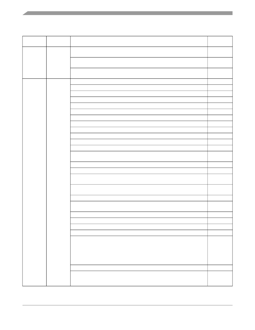
Revision History
MC68HC908GT16 MC68HC908GT8 Data Sheet, Rev. 3
4
Freescale Semiconductor
June,
2002
2.0
Figure 2-2. Control, Status, and Data Registers — Corrected ESCI arbiter data
register (SCIADAT) to reflect read-only status
Figure 14-19. ESCI Arbiter Control Register (SCIACTL) — Corrected address
location designator from $0018 to $000A
Figure 14-20. ESCI Arbiter Data Register (SCIADAT) — Corrected address
location designator from $0019 to $000B
Reformatted to meet current publications standards
1.5.6 ADC Reference Pins (V
REFH
and V
REFL
)
— Corrected connections
2.6.3 FLASH Page Erase Operation
— Updated procedure
2.6.4 FLASH Mass Erase Operation
— Updated procedure
2.6.5 FLASH Program/Read Operation
— Updated procedure
2.6.6 FLASH Block Protection
— Description updated for clarity
3.3.5 Conversion
— Updated for clarity
3.6.3 ADC Voltage Reference High Pin (V
REFH
)
— Corrected connections
3.6.4 ADC Voltage Reference Low Pin (V
REFL
)
— Corrected connections
3.7.1 ADC Status and Control Register
— Updated description of the COCO bit
Chapter 4 Configuration Register (CONFIG)
— Updated COP tmeout selections
Chapter 4 Configuration Register (CONFIG)
— Updted SSREC bit usage
Chapter 5 Computer Operating Properly (COP) Module
— Updated timeout
selections
Figure 5-1. COP Block Diagram
— Updated illustration for clarity
Table 6-1. Instruction Set Summary
— Updated definitions for STOP and WAIT
Figure 7-9. Code Example for Switching Clock Sources
— Replaced example
code
Figure 7-10. Code Example for Enabling the Clock Monitor
— Replaced example
code
Figure 14-18. ESCI Prescaler Register (SCPSC)
— Corrected address location
Chapter 15 System Integration Module (SIM)
— Clarified SIM features and
functionality
15.7.2 SIM Reset Status Register
— Clarified SRSR operation
Table 19-1. Monitor Mode Signal Requirements and Options
— Reworked
19.2.1 Functional Description
— Corrected Break description
19.3 Monitor Module (MON)
— Reworked
Chapter 20 Electrical Specifications
— Revised/added tables:
20.5 5.0-V DC Electrical Characteristics
20.6 3.0-V DC Electrical Characteristics
20.7 Supply Current Characteristics
20.8 5-V Control Timing
20.9 3-V Control Timing
20.20 Memory Characteristics
— Updated memory table
Chapter 20 Electrical Specifications
— Added figures:
Figure 20-1. RST and IRQ Timing
Figure 20-2. RST and IRQ Timing
50
170
171
September,
2004
3.0
Throughout
24
39
40
41
43
50
51
51
52
55
,
57
58
60
59
68
87
88
170
177
,
180
,
181
,
182
192
245
235
,
238
241
255
256
257
258
258
271
258
258
Revision History (Sheet 2 of 2)
Date
Revision
Level
Description
Page
Number(s)
相關(guān)PDF資料 |
PDF描述 |
|---|---|
| MC68HC908QT1 | Microcontrollers |
| MC68HC908QT2 | Microcontrollers |
| MC68HC908QT4 | Microcontrollers |
| MC68HC908QY1 | Microcontrollers |
| MC68HC908QY2 | Microcontrollers |
相關(guān)代理商/技術(shù)參數(shù) |
參數(shù)描述 |
|---|---|
| MC68HC908GR8ACFA | 制造商:Rochester Electronics LLC 功能描述:- Bulk 制造商:Motorola Inc 功能描述: 制造商:MOTOROLA 功能描述: |
| MC68HC908GR8AMFA | 制造商:Rochester Electronics LLC 功能描述:- Bulk |
| MC68HC908GR8AVFA | 制造商:Rochester Electronics LLC 功能描述:- Bulk |
| MC68HC908GR8CB | 制造商:Rochester Electronics LLC 功能描述:8 BIT MCU, 7.5K FLASH - Bulk |
| MC68HC908GR8CD | 功能描述:8位微控制器 -MCU 8 Bit 8MHz RoHS:否 制造商:Silicon Labs 核心:8051 處理器系列:C8051F39x 數(shù)據(jù)總線寬度:8 bit 最大時(shí)鐘頻率:50 MHz 程序存儲(chǔ)器大小:16 KB 數(shù)據(jù) RAM 大小:1 KB 片上 ADC:Yes 工作電源電壓:1.8 V to 3.6 V 工作溫度范圍:- 40 C to + 105 C 封裝 / 箱體:QFN-20 安裝風(fēng)格:SMD/SMT |
發(fā)布緊急采購(gòu),3分鐘左右您將得到回復(fù)。